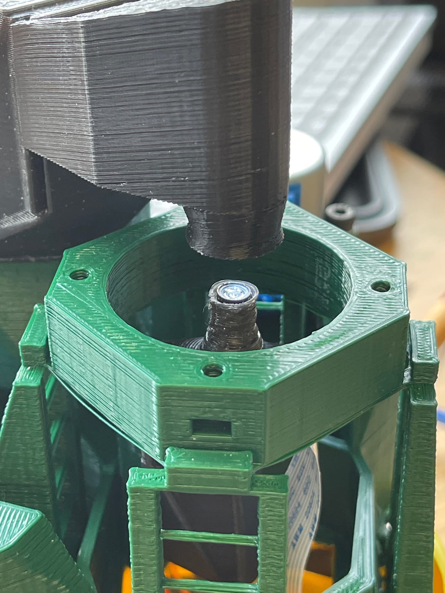
Hi everyone. I was seeking for the collective knowledge to help me on this issue. I built the new low cost V7 microscope using the pi lens spacer as the optics module. I am getting this funny looking halo which get worse after doing the auto calibration. I tried different types of LEDs but that did not help.
after playing around with the setting I get it a little bit better
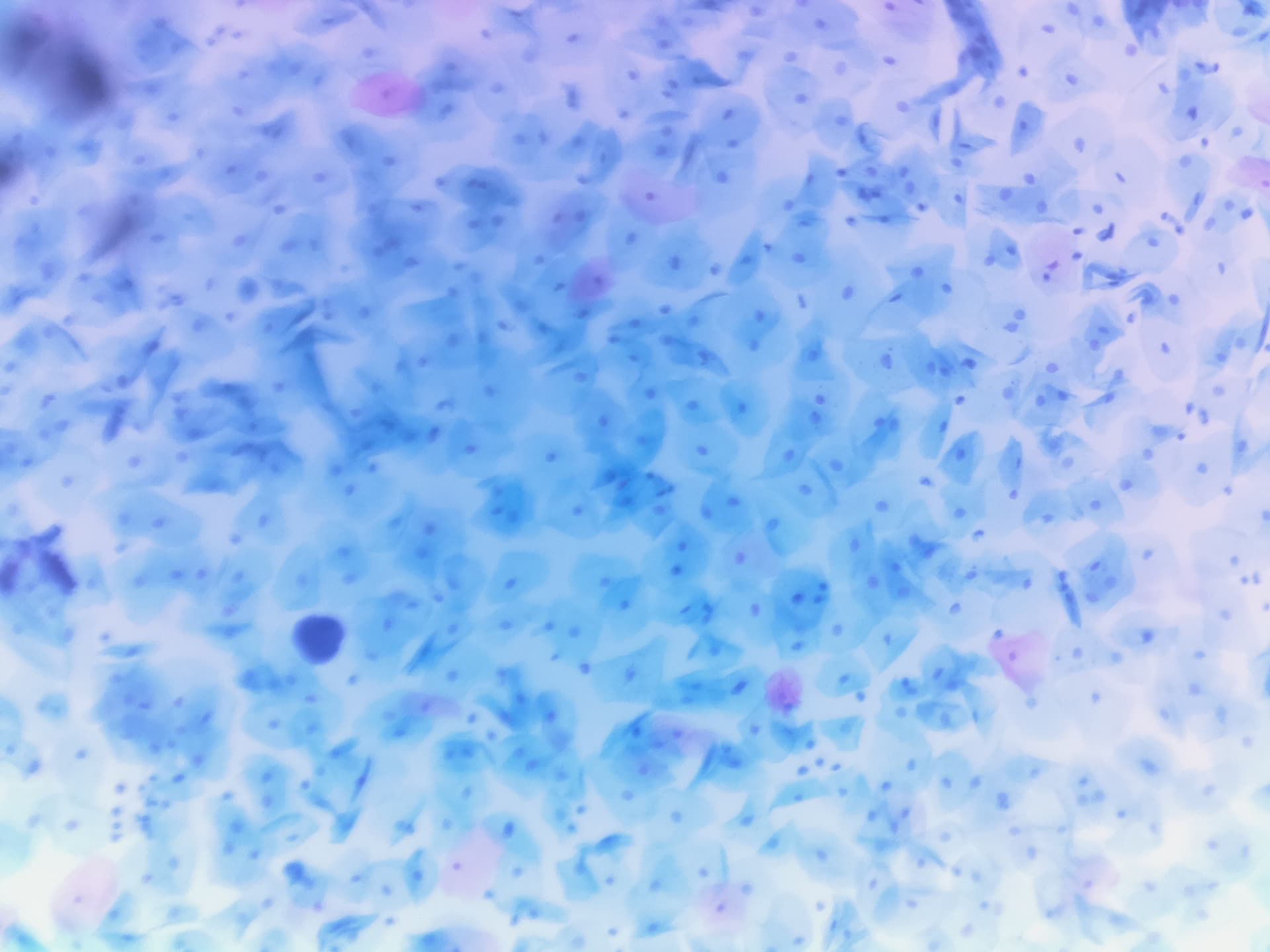
but the images came blurry
That is not nice. Which version Openflexure server is it running? It should say in ‘about’ in the Web App.
version 2.9.3.
What is the recommended distance between the LED and the lens? I found is kind of tricky to sit the 5mm LED in the center of the condenser tube. The light beam that comes out seems adequate though
I have that coloration too. Though I use Libcamera to take pics instead of openflexure (so no autofocus and whatev else).
This image is garlic skin so supposed to be white.
I use a NoIR camera if that makes a difference, but my achromatic lens cuts out UV/IR. If I turn the room lights off or add an extra UV/IR filter it doesn’t change the colors. If I add an IR-pass filter (blocks visible light) it can’t see anything, so it’s not IR.
Edit: more experiments. This one is still garlic skin but with a less corrected color profile:
The saturation varies, so SOME of it is auto-gain.
I took a vid using libcamera-vid and I think it just has a better color profile, the discolored spot in the center is lessened. The video mode uses a smaller sensor area so the discolored spot is bigger.
Here’s a photo before I stuck it in the microscope, not the best photo so idk what to make of it, the color profile or gains make it a bit pinkish.
I am using a Picamera NoIR too but with the lens spacer. I have another microscope with a 20x objective and I see the same halo effect. My guess is that this is not a problem with the software. Perhaps the condenser needs a diffuser lens to make the light move even. the LED wavelength? adding a ND filter? I dont know
@Heartyhar the colouration that you see when not using the OpenFlexure software is because of the built in hardware design and software corrections to give an image with good colour reproduction when using the intended lens in its intended use as a camera with a built in IR filter. The No-IR camera I think does give the pink cast that you see when used as a camera. Using the camera sensor as a microscope changes the colour casts. The calibration function in the OpenFlexure software measures the colour and shading on an empty image and then corrects for it, as in the images in OpenFlexure Microscope Stack and Scan Video - General - OpenFlexure Forum
@dgrosen if you are on the latest software 2.10.0 or 2.10.1 then the colouration is surprising and we need to work out why it is happening. There were inconsistencies in calibration in version 2.9, which should all be fixed in 2.10.
Note, the pre-built SD card images are still dated 2021-06-17, which is before the v2.10 release. You will need to upgrade once you have built a new microscope.
sudo ofm update
sudo ofm upgrade
(see Software release v2.10.0 - Announcements - OpenFlexure Forum)
[edit: I missed your previous post @dgrosen. The upgrade from v2.9.3 to v2.10.1 should make it all work.]
Thanks William, good to know the cause. If I ever need to use this microscope seriously I’ll get a second SD card and install the Openflexure OS on it.
Even for non-serious use, the colour correction makes viewing much more pleasant. The colour correction is a library that @r.w.bowman devised and can be used outside the Openflexure software, but unfortunately not on the latest Raspberry Pi Raspbian releases that use libcamera. From the other thread I think you are on a Pi Zero 2W? This should be able to run Openflexure Lite, without desktop, but will not be up to the task of displaying Raspbian desktop.
Yes it’s the Pi Zero 2. It has the same processor as the Pi 3 (but less ram). It has no problem with the full ras pi desktop OS so I’m 99% sure it will run the desktop openflexure.
I did the ofm upgrade and update and these are my results. I tried 3 different LEDs. The one with the red arrow gave me the best results on the other microscopes.
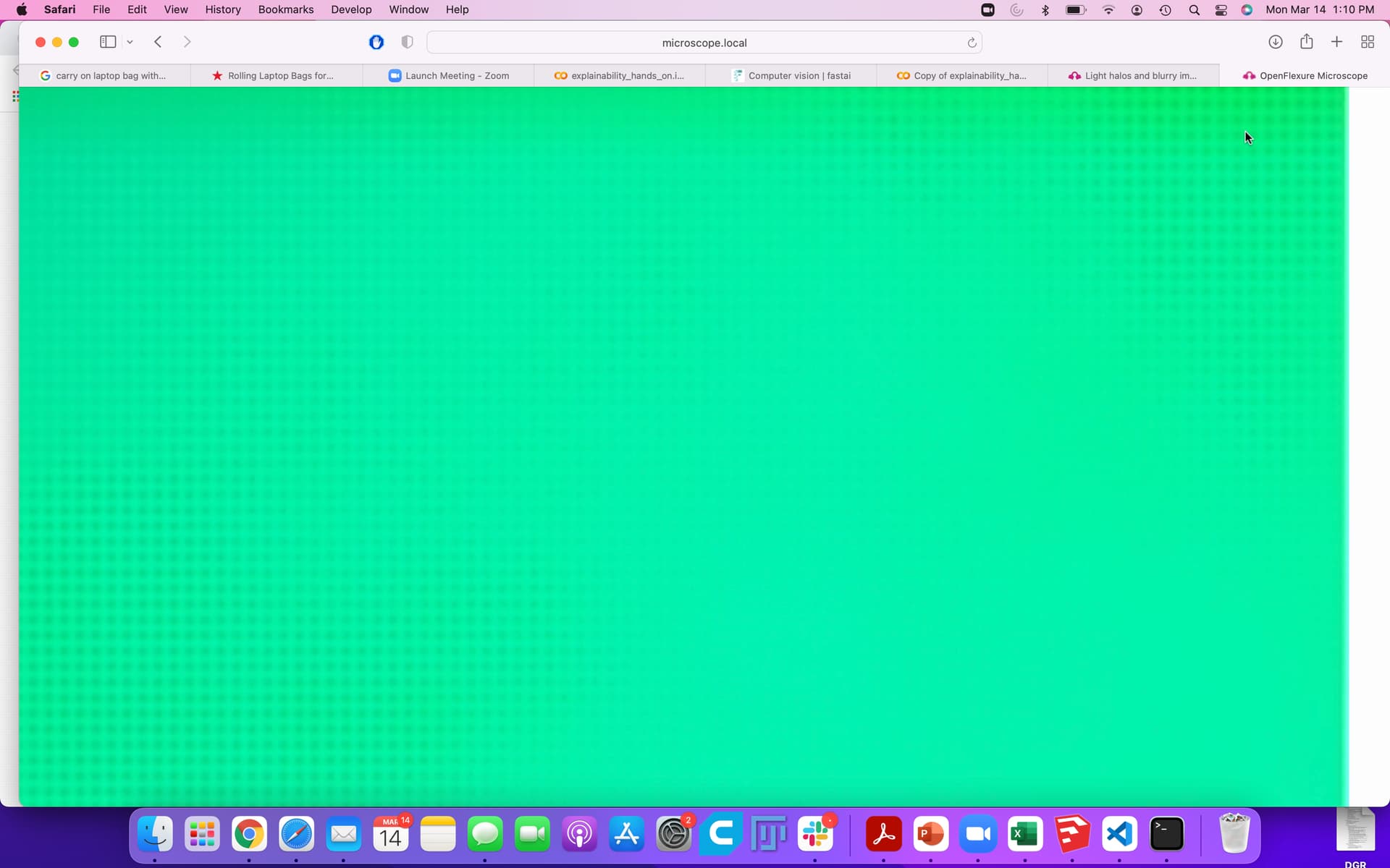
I am not getting even illumination regardless on how I position the condenser.
In this loop I started with a green image which does not get better after full calibration.
I also get the funny looking grid pattern
It can not be that tricky to get even illumination. I am puzzled.
I tried with a pi zero 2 and it kind of works. However, it is painfully slow to run the raspbian desktop
Oh dear, that does not look good. There was actually a similar thread last August Blurry green image - Request Help - OpenFlexure Forum which was after when we had the 2.10.0beta, so the old green problem from v2.9 should have gone away.
@r.w.bowman, could this be previous calibrations not being wiped properly? does disable flat-field correction wipe everything including exposure?
Looking at the gif, and the settings it shows, I think we are seeing saturation here, even with a very short shutter speed. That suggests you have extremely bright illumination - what optics are you using, and what LED? You must have found a really bright one I think! If you’re saturating the illumination, that will confuse a lot of things - could you use a dimmer LED, or perhaps diffuse it by sticking some white PTFE tape over the LED? If you deliberately misalign the condenser (e.g. by moving it upwards) do you see it improve? Also, is your illumination green, or white? If you’re calibrating with single colour illumination, it is very likely to get confused, @samuelmcdermott may be able to comment on how well the 2.10 calibration works for single colour illumination.
I think you may be right. This is probably a very bright LED. I will try to adjust the brightness using pulse weight modulation.
For those interested you can connect your LED to pin 4(5v) and the other to pin5 (GPIO 3)
run this code
import RPi.GPIO as GPIO
GPIO.setmode(GPIO.BOARD)
GPIO.setup(3, GPIO.OUT) #this is set to GPIO3. change the number is you want another pin
P=GPIO.PWM(3,100)
P.start(50) #50% brightness. Adjust this number to increase or decrease the brightness.
Quick update…Did not work 
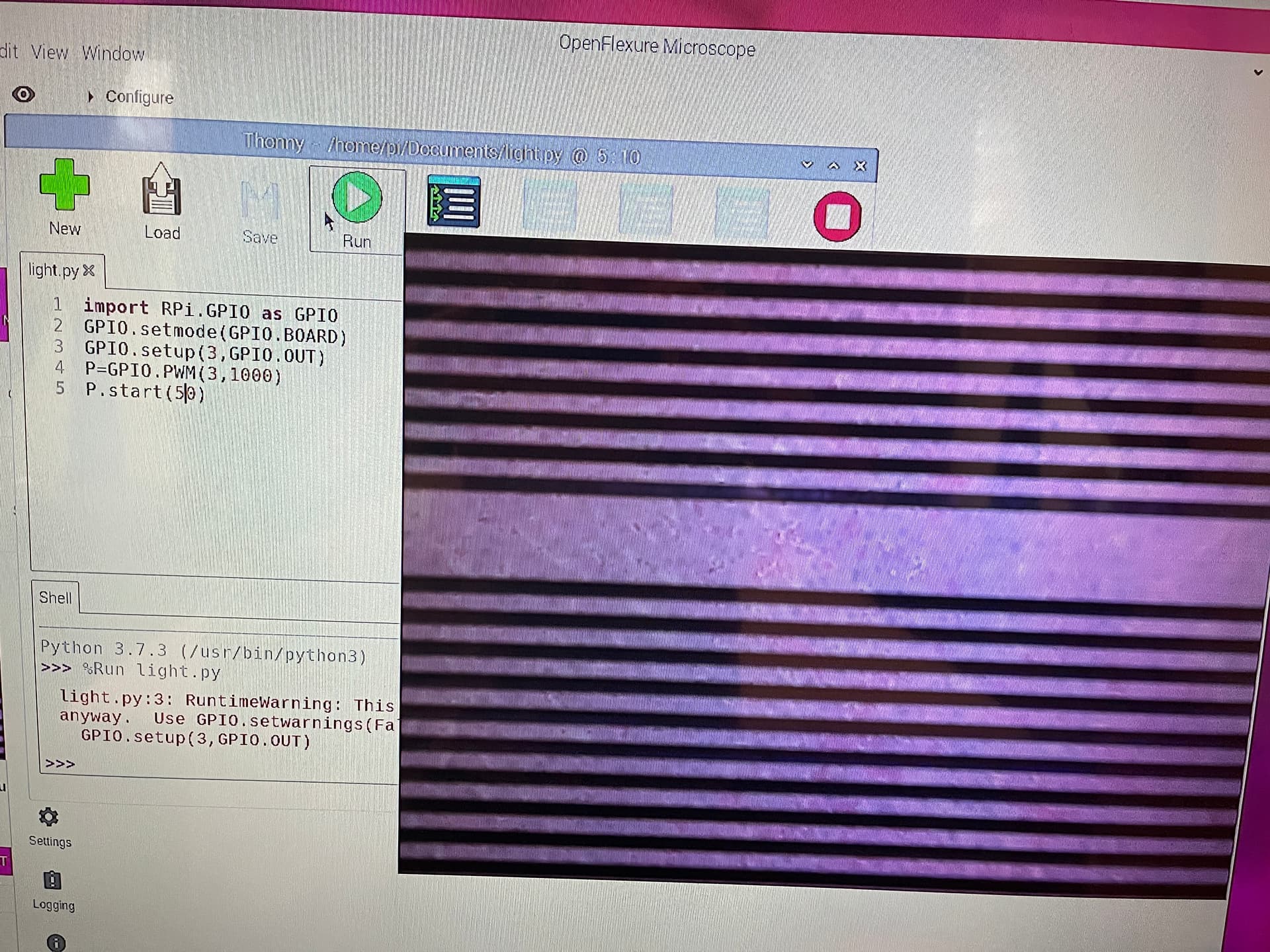
This approach makes the LED flicker creating horrible horizontal black bands. I will post a pic later.
@dgrosen I am not too familiar with the RPi PWM but the effect that you describe would happen if the PWM frequency is too low. The on and off time of the LED is long enough for it to be on for some lines and off for others during the camera frame capture. You should be able to set the PWM to quite a high frequency so that this does not happen. I don’t know where in the GPIO commands this is set. Searching seems to suggest that it is the 100 in P=GPIO.PWM(3,100) giving the frequency as 100Hz. That would certainly give the effect that you describe and needs to be higher. I don’t know how high the Pi will allow it to go. 1000 Hz would be better, 10000 or more is ideal.
I will try that. Hope I don’t create a time portal.
I found this article to generate software and hardware PWM. Somewhere I read that using C is much faster and does not create flickering.
The hardware PWM is likely to go to higher frequency, but I am struggling to find the maximums for the GPIO.PWM, which seems to be a software PWM. Hardware PWM libraries seem to be available for Python, not just C.
Hardware PWM is also more precise, but that is not so necessary for dimming and LED.
That is not useful, but really cool. Clearly needs to be even faster to work for dimming, which will need hardware PWM. From the top picture you will need to go to a pretty high frequency. Or you use the resistor dimmer from the other thread that you posted in.
The inconsistency of the software PWM is clearly seen in the images in ‘missed’ dark bars. It is interesting that there are no extra wide dark bars.