I’m still waiting for my optics and for a soldering iron/solder so I can finish building the motor driver, but I’m excited to so I put it together already. Will update once I get the optics.
I don’t really need a microscope but I very much wanted to build one, and I know a few biologists in Venezuela who could use one so I’m going to try to get some into the country. So, thanks for the amazing work that has gone behind making this!
Electronics and optics: Still in progress. (btw, I think an image like this one could be useful in the build instructions for the alternative motor control electronics - it’s pretty clear once you start putting it together, but I’ve seen a few people ask about it).
I had a bicycle accident so it took me longer than I expected to get to this point, but here we are…
Now, I’m at a loss. How does the Nano communicate with the Raspberry Pi? It’s not detailed in the instructions. The Sangaboard connects directly to the Raspberry Pi GPIO pins, but it’s not clear what pins from the Nano to connect to the Raspberry, or if the communication is supposed to happen via USB-C? The instructions arnt too explicit on this part.
Edit: Oh! I just found a different set of documentation which has more details here - OpenFlexure Documentation
“connect the Arduino to your microscope’s Raspberry Pi via its USB port.” mkay, lets see about that…
edit: Wanted to add that I’m not sure what the converter plate gripper is for. I havn’t used it so far.
I decided to carve out a hole on the side of the electronics to pass the USB power for the steppers. Looks bad but it should work. With this all of my electronics are ready, except the illumination. I also need a USB-C cable to connect the Pi to the arduino, and it seems the USB-C in this knockoff arduino I got is way too lose… might be a problem. We’ll see.
Coming along well. The Nano indeed connects using USB. Usually that is a micro-USB, but yours is USB-C. The Nano is 5V logic so cannot connect directly to the 3.3V Raspberry Pi pins.
The gripper is to hold the Nano on the plate. There is a screw hole in the plate at the back end of the Nano for a self-tapping screw.
Oh! Of course, I see it now. Oh well, maybe for the next microscope. For now I fixed the nano in place with some molten PLA - not pretty, but it should work.
Optics finally got here, now all I’m missing is the illumination PCB… but maybe I can try it with some alternative illumination source.
I’m a bit worried tho, as per the instructions I pushed the objective as high as it would go, but I feel that it’s sticking out a bit too much past the plate holder. Is this normal?
If you install the openflexure os image onto the raspberry pi, the microscope will be automatically connectable over the network without any need to set anything up manually btw.
How so? I just flashed the OFM Raspbian to an SD card and plugged it into the Pi. During flashing I configured my network and password, hostname, etc., but trying microscope.local returns nothing.
I just got a notification that the raspberry pi is connected to my network… but I still can’t reach it.
Edit: Doh! Nevermind, I just looked up the Rpi IP adress, and put that in, and now I’m connected! Time to debug…
Wellp. Now I’ve got a “camera disconnected” error to deal with, and no motion on the stage; let’s see…
Make sure you have a good connection to the camera and if you have access to a multimeter I would check to make sure the proper voltage is being delivered to the motor boards.
Swapped the camera and this one seems to work, now lets try to remove the lens and see if I dont ruin it… Done! Got a working camera mounted on the optics. Now to fix the motor stage…
Progress! Got the camera working, and it seems the motors as well - though still not moving. I think the USB cable I tried to use to power them is too thin, as the voltage at the motor ends was 3.6V - it shouldnt be too much current draw as the supply is rated for 3A and these allegedly draw 240mA a piece - I need something thicker.
OOOOH we got motion - I was right, just needed chunkier cable for the motors. Looks like I’ve got a nearly functional microscope. Only missing the ilumination. I tried doing a test run with a few white LEDs I have lying around but… the screen would just turn green for some reason?
Edit: Well, thats gone. I must have burnt out my power supply? And none of the others I have works? I can’t get any motion anymore - the motor drivers seem to partially light up but nothing happens. I’ll try to get a bigger supply tomorrow.
Also, I managed to drive my Z stage even further up, instead of down, for some reason. I tried giving negative coordinates, but it didn’t work - and neither did reversing the axis (though that might have to do with my power supply).
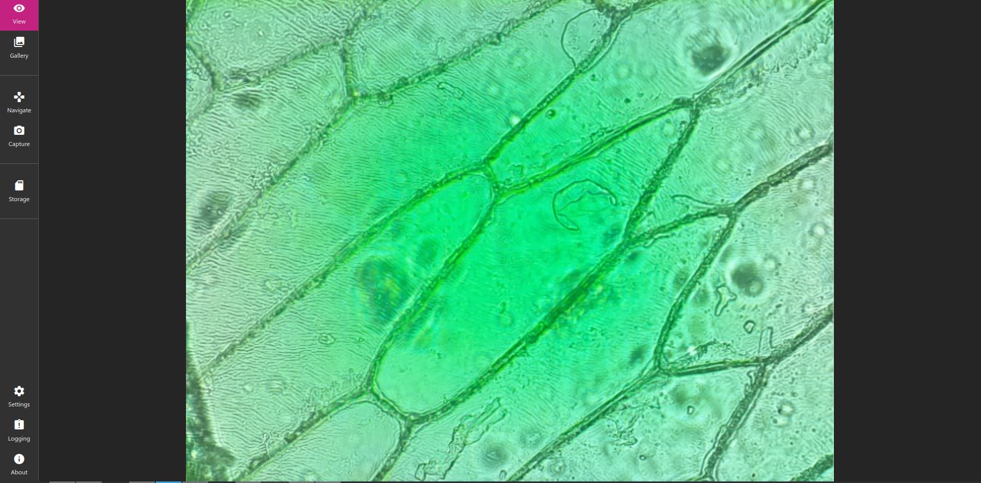
Edit2: Took off the Z motor and manually moved the stage just to test it out. I havn’t been able to focus on anything other than what I think are imperfections on the glass slide, and everythings got this weird green tint - but at least it looks like a microscope image.
Image calibration will fix the green tint. If your unable to focus on your slide make sure you have it flipped the facing down and you have the correct part of your slide over the objective.
Doh! Last time I used a microscope was in grade school, so of course I put the slide upside down. After setting it the right way around, I can finally see my onion cells!
Out of curiosity, is it possible to include a scale in the image? It would be great to use this to measure things.
Did you calibrate it on a blank image with no slide in place?
I don’t think a micrometer is available because it would differ for how each person set up their microscope, but I see how the feature could be implemented with a calibration slide though.
Yeah, I calibrated with no slide in place, just the illumination. I’ve repeated the calibration a bunch of times with no luck. Sometimes it seems it’s trending towards white, and then at the last second it changes to bright green.
Ok this one is probably beyond my abilities, but here’s my last idea.
I don’t have my microscope nearby but if I’m not mistaken the flat field correction is separate from the calibration. I would try flat field then calibration or the other way around.