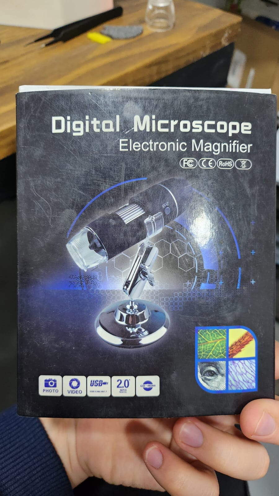
I’ve purchased a microscope kit (except for the 3D printed parts) and got really nice results! I’m still getting to know the software (for example i saw a post that talked about image stiching and i didn’t see that in the soft).
Anyways, i realized that i chose the wrong microscope as i plan to see non-translucent stuff (mostly foams, fabrics and so) and i can’t see them at all. Also, the x40 objective has a really small focus that makes hard to understand foam and “3D things”.
By now i understand that i should have chosen a reflaction microscope, so i thought well then, i can just adapt this right? But no, i need at least a beam splitter that seems imposible to get in Argentina.
I’m trying to convert it using a microscope glass slide as a beam spliter but got really bad results, can you give me any idea on how to solve this?
Hi @guardio. Reflection should work to some extent with just a glass plate as the beamsplitter. You will lose a lot of light, which might mean that it is too dim. There will also be a strong illumination through the beamsplitter onto the back wall inside the optics module. This is black, but is flat and can be quite shiny. The scattered light reflects from the beamsplitter and onto the camera, causing a washed out image.
Some people have made it work in that way. I think there are also some posts about this reflection mode in the long thread on fluorescence microscopy.
What is the length scale you are trying to look at. If you are looking at larger structures (mm or so) this may be something where the field dissection microscope (a very much less polished project) may be of use:
Well the foams have holes of around 0.25mm and i’d need to see like a 30x30mm square ideally, i planned to use the 12x12mm scan capability of the microscope and just extrapolate. Really 10x10mm of field of view would be enough (and amazing).
I saw the pictures of the attached microscope (flower and screw) and it seems that they are way too big if i’m right, i’d like to hear from you.
I ended up trying the cheap optics (RPi V2 with its own lens), but I ran into the same issue: too small a field of view and depth of field.
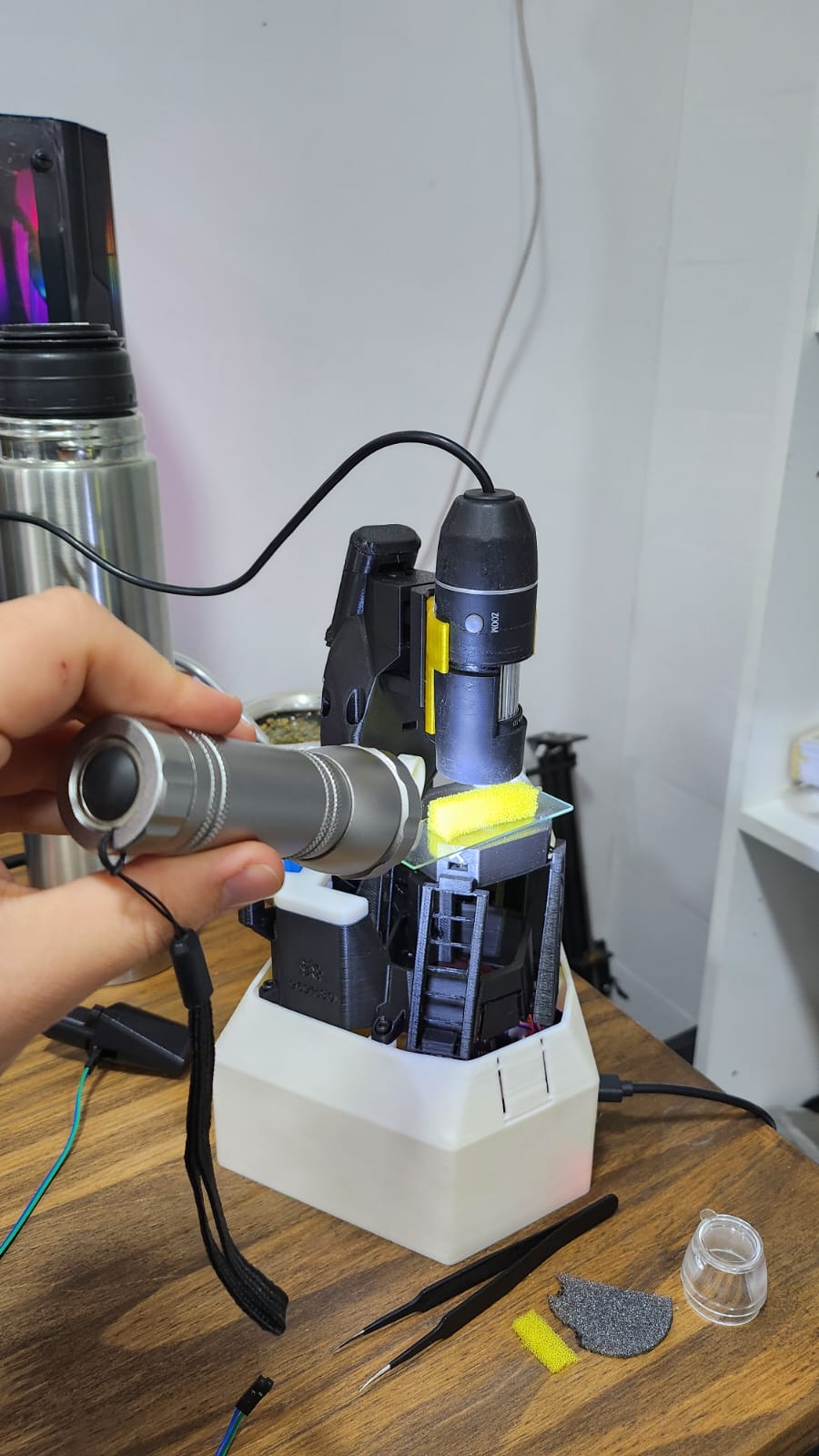
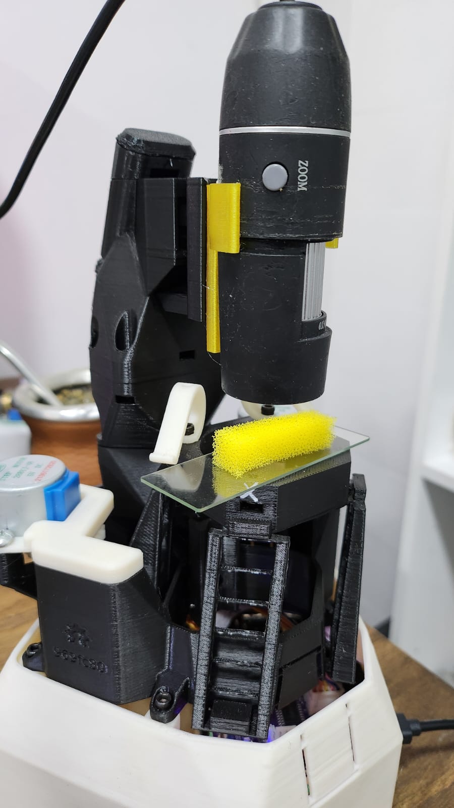
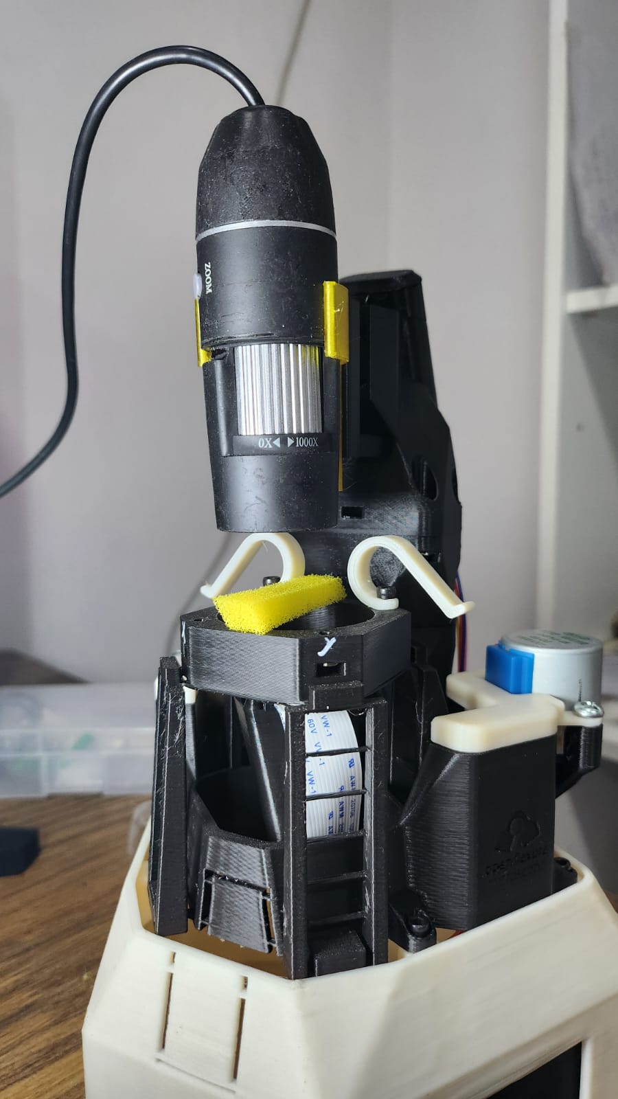
In the end, what worked was designing a new part to adapt it to a cheap toy microscope we had lying around. As you can see in the image, it almost feels like a shame to use such a well-designed architecture with these optics — but for the required magnification, it works great!
For illumination I’m using a novel (just kidding) solution: I hold a flashlight by hand next to it. I’ll set up something more permanent soon, because it’s not fun keeping my hand there for that long.
I’ve uploaded the STL file here in case someone else has a similar need.
I read in the docs that the software isn’t compatible with a USB camera, so I’m currently running it from Windows. Is there any way to make it work so I can do scans?
Thanks again, and I hope someone gets a good laugh out of this.
Also, thanks to @nanocastro for the help — I’ll reach out to you, since I realized while writing this that I completely forgot about the other camera.
That might be possible. It depends how well you can detatch and re-mount the lens. On one of the Dissection Microscope threads there are some images that show about the same field of view that you have (yours looks about 4mmx3mm), maybe a bit bigger. A different M12 lens or spacee shoud get to what you want. You could mount that camera relatively easily onto a modified camera_platform on your microscope.
I think that someone has also made a version of the lens spacer like the low-cost optcs, but with the lens much closer to the Pi Camera for a bigger field of view.
I wonder if you should just switch to a 4x or 5x objective - may be even 2x or 2.5x if you can find them. They should have enough working distance to get enough light in from the side - e.g. by putting an LED ring around the objective.
But this sounds like you might be better of with a stereo microscope which have something like a 0.7 - 4.5x zoom objective (times 10x for the ocular) and can be fitted with a 0.5x or 2x Barlow lens.
That’s great @WilliamW, I’ll definetly try the flat top microscope optics configuration from @biodotpe, I’d like to modify it to have a similar FOV as now of 4mm x 3mm, I saw that the lens is used in his microscope the “right way” and in the cheap optics microscope is “upside down”, what’s the influence of that and how can i know where and in which side to set the lens? I think that would be a really usefull calculation for makers!
Hello @ffesti , thanks for the suggestion, sadly I’m from Argentina and lenses here are not available or common to buy, also we’d like not to spend more money if it’s possible.
When the Pi Camera is used as a normal camera, the lens is close to the sensor and the scene is far away. This is taken into accoint in the lens design.
In the OpenFlexure lens spacer the lens is closer to the sample (~1mm) than it is to the sensor ~15mm), so we turn the lens round.
In the one that I linked to, the lens is closer to the camera than to the sample, so it is not turned round compared to the designed direction.
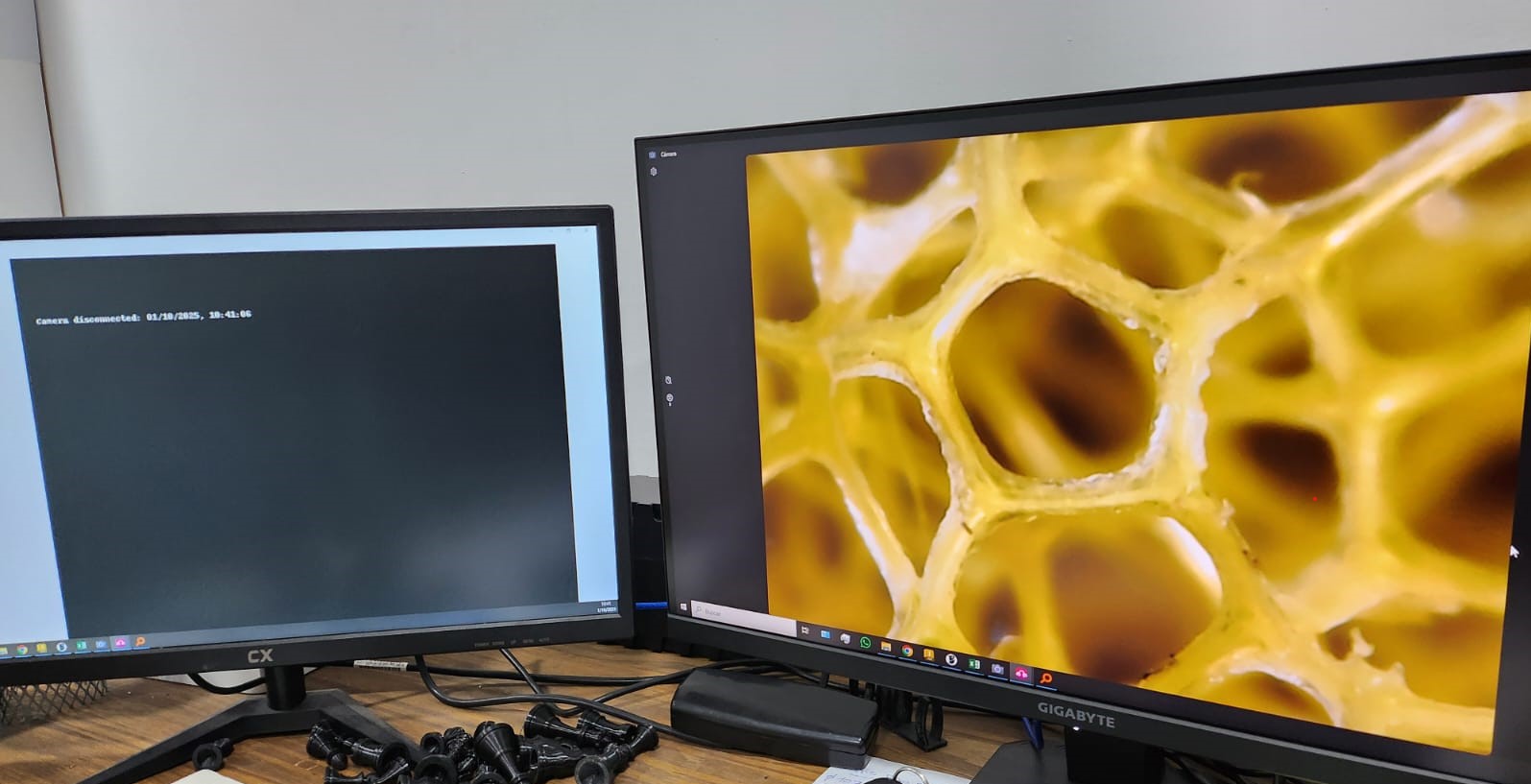
Hello @WilliamW , thanks for the info. I ended up trying the lens in the max position of the thread, so I don’t have any extra component. I also set up both cameras at the same time with a exterior light (as you can see in the monitors).
I think I’ll leave it that way for now, until I need the X40 objective.
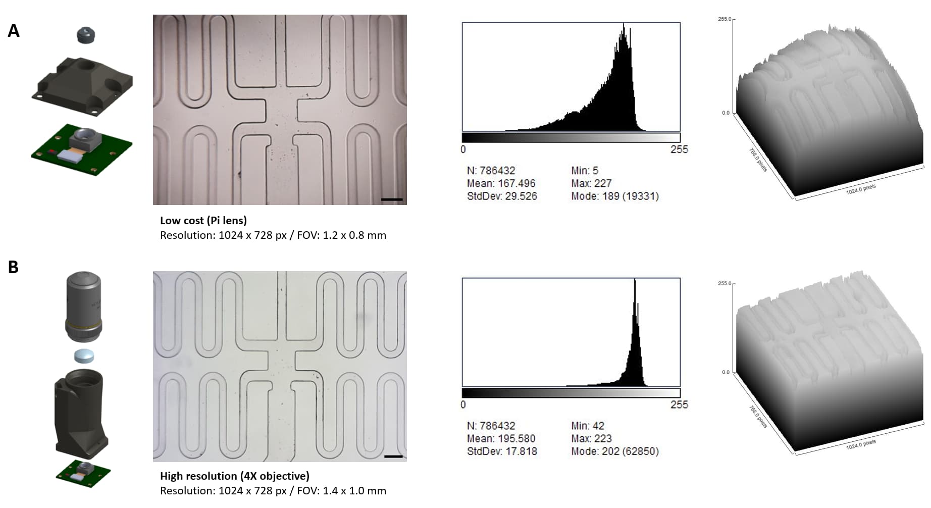
Hi @guardio I tried a laser lens with the Pi cam in the past and I achieved a 3 x 3 mm FOV. I decided to use the Pi lens because of the higher contrast and resolution.
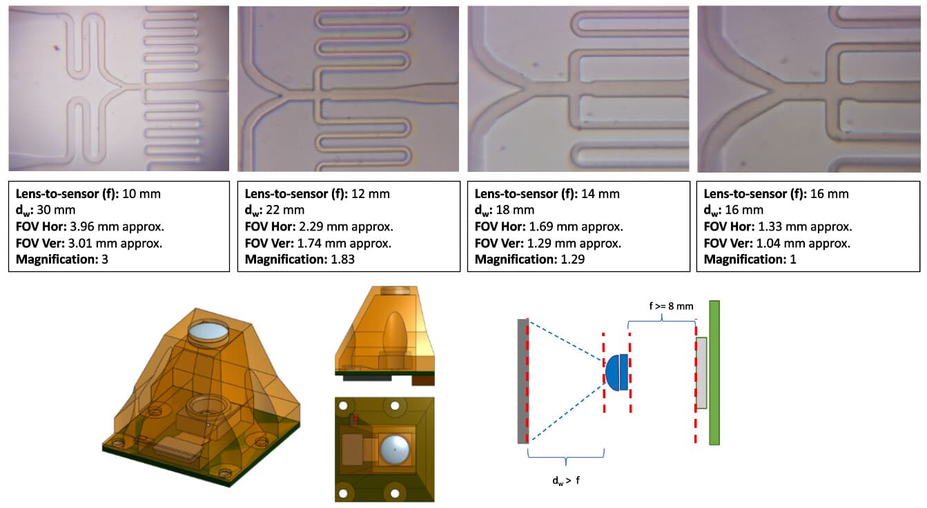
The optics configuration I proposed for our flat-top microscope design is similar to a 4X objective. The limitation of this configuration is the vignetting and out of focus on the edges (scale bar: 100 um).
Looks like the magnification numbers in the first graphic are the wrong way round. The first one has a magnification of 1/3 not 3. The field of view is bigger than the sensor. Same for all the others.
The tube lens in the high resolution optics reduces the magnification. This is why the 4x objective is similar to a 1.2x magnification.
‘Magnification’ is a term with many meanings, depending on the reference. The ‘4× lens’ is defined in the context of a standard microscope with eyepieces. In a digital microscope, the equivalent magnification is usually thought of as the equivalent size of the field of view. The tube lens is used to make the field of view in the OpenFlexure optics the same as in a microscope with eyepieces. It ends up looking a bit smaller because it is a rectangle, not a circle.
In the set of images above the magnification is relative to the smallest field of view in the set, which is very different basis for the 1.2× number.
Hello @nanocastro ! I gave them to your friend, I believe they are on the way!
@biodotpe That’s really handy to have as an option, I’ll have it in mind but not use it right now as we’re content with the actual config (and we don’t want to spend more time in this now).
May I ask why we’re just “trying” new configurations of the optics and not just “calculating” them? Are them difficult, We don’t have some data, etc?
Also, your depth graphs look amazing, how did you do them and the histograms?