That’s a neat approach - can you just slice the support STL in any old slicer and it will work? If so, it would be super to know how you generated it. The need to sit everything on the print bed is an annoying limitation, so it’s definitely worth knowing if my assumption that it’s a fundamental limit is not right!
Thanks. As long as you can remove the support later, it’s fine to put the intended printed material anywhere you like.
Any slicer of your choosing should works. I never trust the auto-generated support, especially with part with this much bridging areas so it’s built-in. I intended for my variant to be printed between 0.3-0.35mm nozzle and 0.16-0.2mm layer height.
I made the supports in Solidworks, then edit everything in Netfabb, sliced with Simplify3d (such heretic of me as none of those is open-sourced).
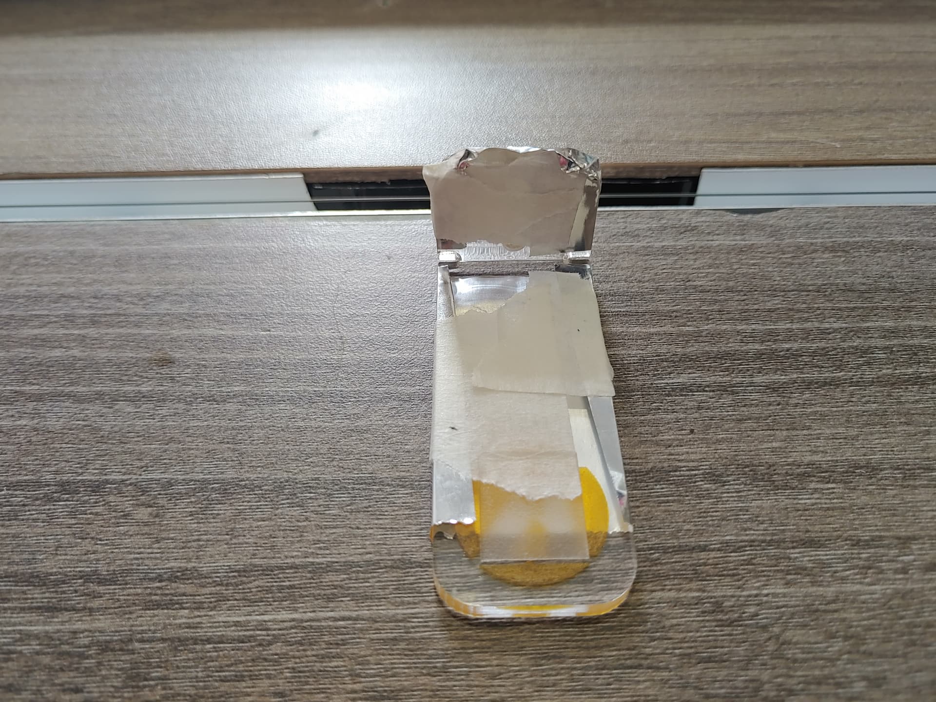
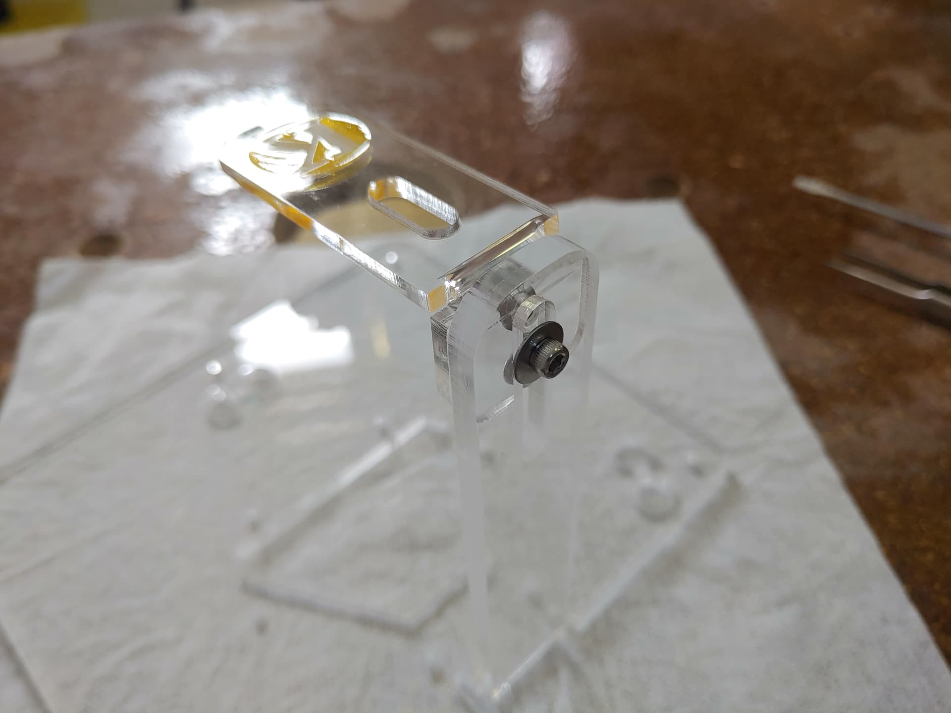
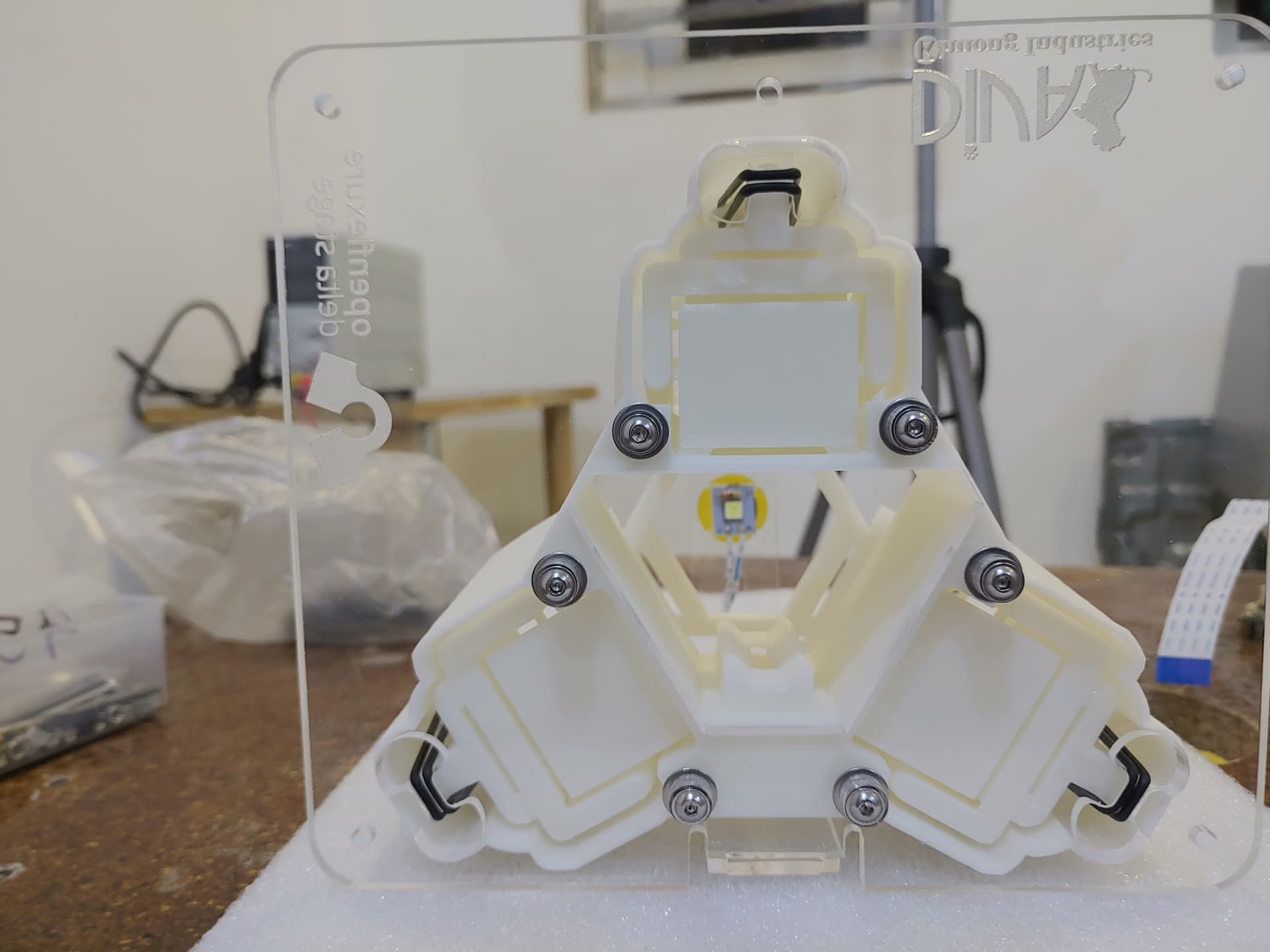
I also like what you’ve done with the acrylic base - we have avoided relying on laser cutting for the core design (because a lot of people have printer but not laser cutter), but a custom plate definitely makes a lot of things better when you come to turn it into something more product-shaped.
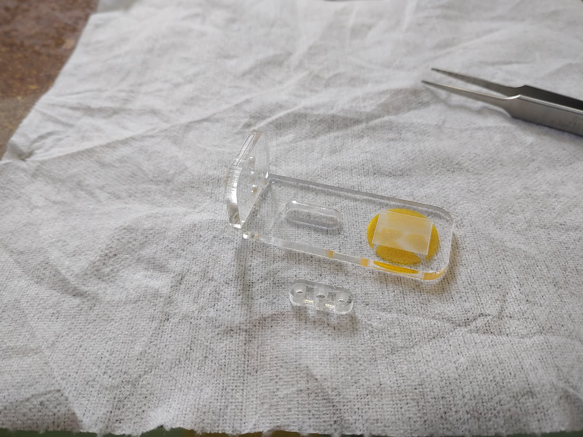
Thanks again. All logos are on the bottom as well to give it a more clean look and also easier to be cleaned. The plate can surely be convert to a 3D print part as well.
Laser cutter and DIY bending machine is a powerful combo that often get overlooked, but that’s a topic for another time and place.
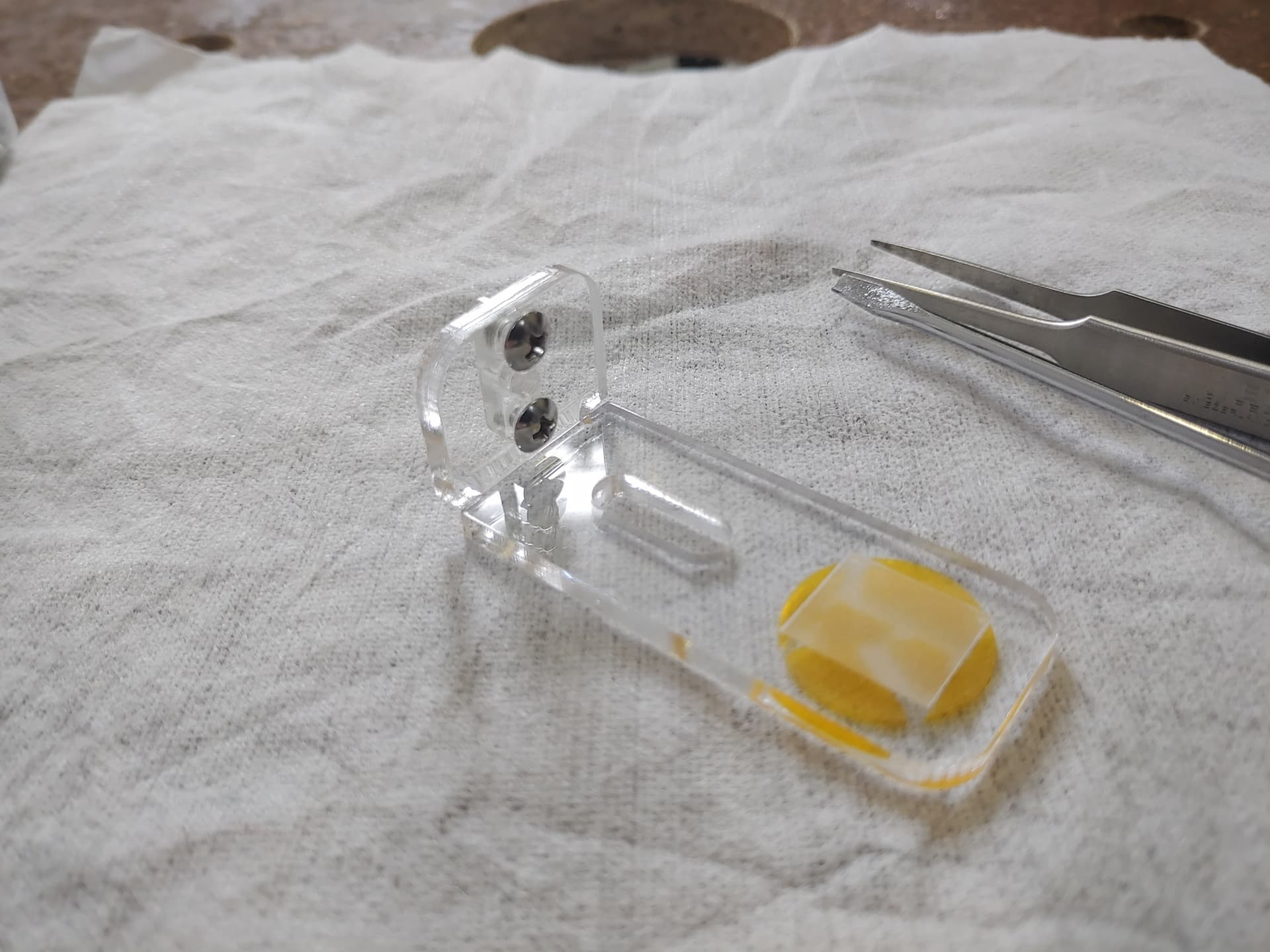
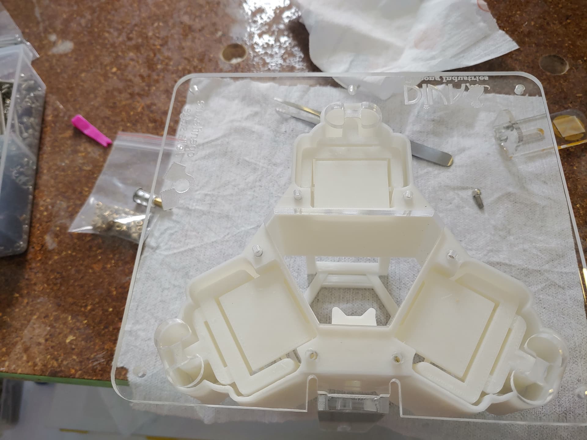
I don’t remember if those 6 mounting holes ever made it into the master branch?
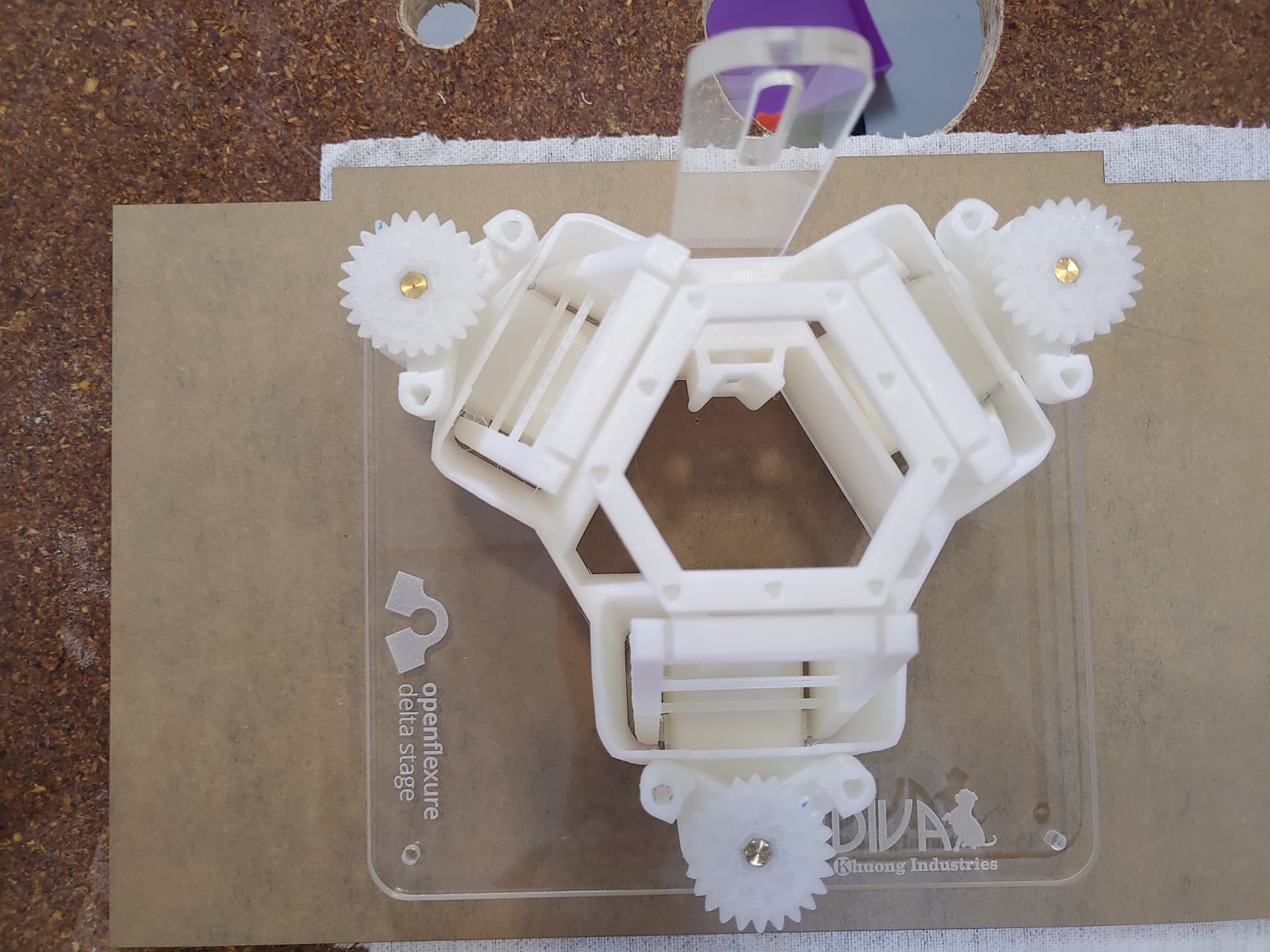
Those have always been there, along with a 7th screw hole under the optic mount. I spent 2 days with openscad but cannot convert the tri-circle function back to actual circle so that was done manually. Tri-circle is not easy to thread tap with cheap hand taps.
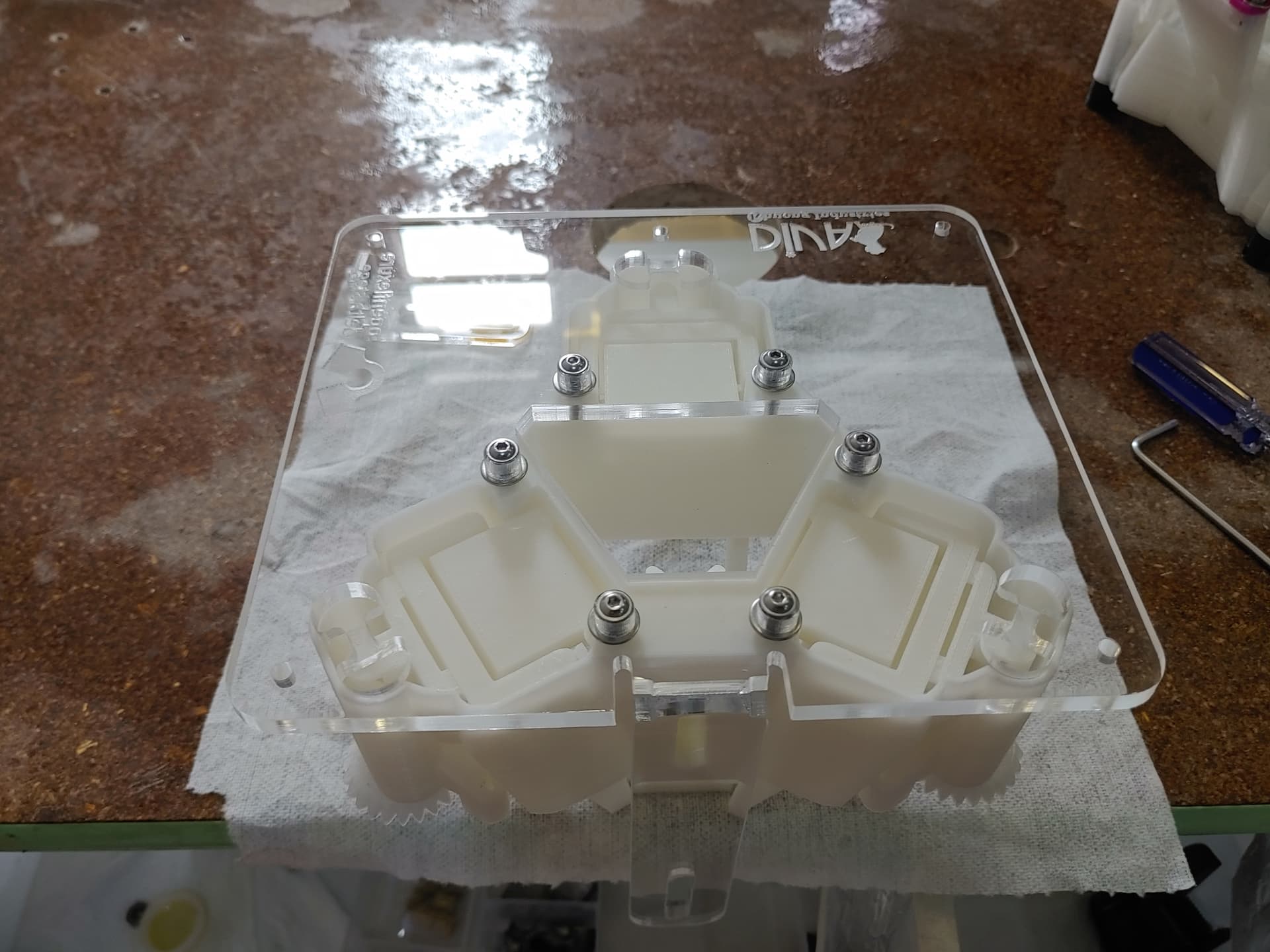
Samuel has now added mounting lugs that would allow you to screw the delta stage down from the top side of the plate. That might be helpful for maintenance, depending on how easy it will be to access screws on the underside of your plate.
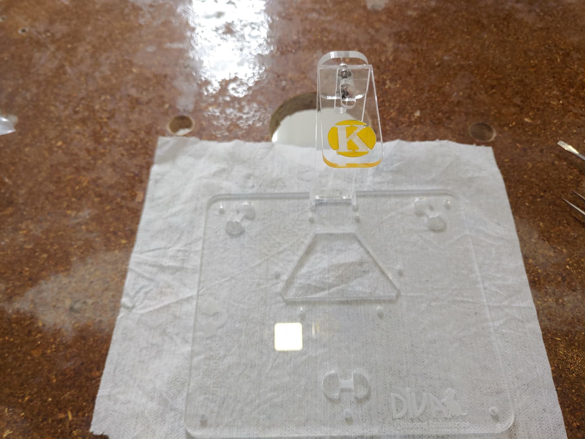
I saw them, the holes outward from o-ring mounts are for the lugs (this build was based on v1.1). They won’t render without -microscope variable which, in turn, also render the illumination dovetail mount. Right now it’s not that important so I didn’t do it. Without the lips from leg part, the 6 mounting holes on bottom are currently for keeping the top plate align with the base. They are required on a 2 mounting plates design.
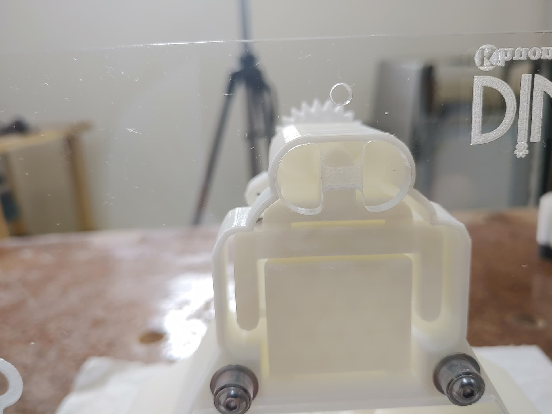
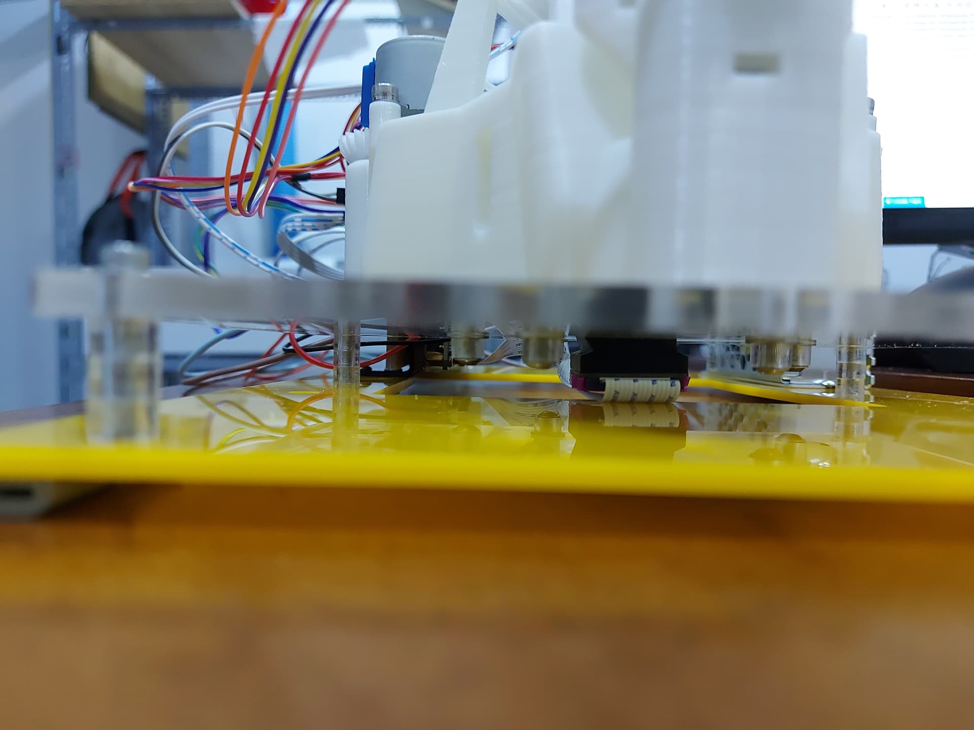
The optics currently protrude downward too much hence the need for 2 plates. My current ideas for next integrations are:
- Use reflective optics but to bend the camera 90°. This is prefered as it move all electronics backward, reduce the height by ~20mm. Require extra prism or mirror → Increase cost.
This also require me to spend many more hours with openscad so the progress has been slow.
- Invert the optics to topside. This shift centre of gravity upward so it’s not elegant at all.
Side note: There another topic about new mount design for optics. I think it’s more important to make it the same for illumination → less parts in total, more compatible between different configurations.
- Extend the base downward another 20mm. This require larger o-rings, increase printing time by hours. In general, absolute terrible choice.
- Keep the 2 plates and use some simple extrude part instead of the standoffs.
Independent from those I’m also looking into:
- Use springs for less ‘sticky’ motion from the o-rings.
- Maybe just keep the flexure and use some miniature linear motion systems for smoother motion and position feedback.
- Maybe sale a package to convert cheap manual microscopes to OFM system. Many vet clinics in Asia have those already. They already have imaging optics so maybe a simple adaptor for Pi camera is enough?