I am a mechanical engineer working at a small composites manufacturer, and we periodically check glass fiber lengths in some of our products. We do this by taking a sample of the molded part and burning off the matrix material in an oven at 600C, followed by measurement of the glass fibers. The fibers are typically on the order of 2mm to 18mm long, so originally we were doing this by hand with a magnifying glass and a ruler. We moved to a cheap digital microscope, but it was still very difficult to get good measurements. This is an important process, but the time involved was much higher than we wanted.
Fast forward to finding and building an OFM. I initially had some problems with our particular combination of 4X objective, possible malformed 50mm achromatic lens, and lighting, but greatly appreciate the feedback I got from @WilliamW and @j.stirling. With some modifications to the optical module, I got focus.
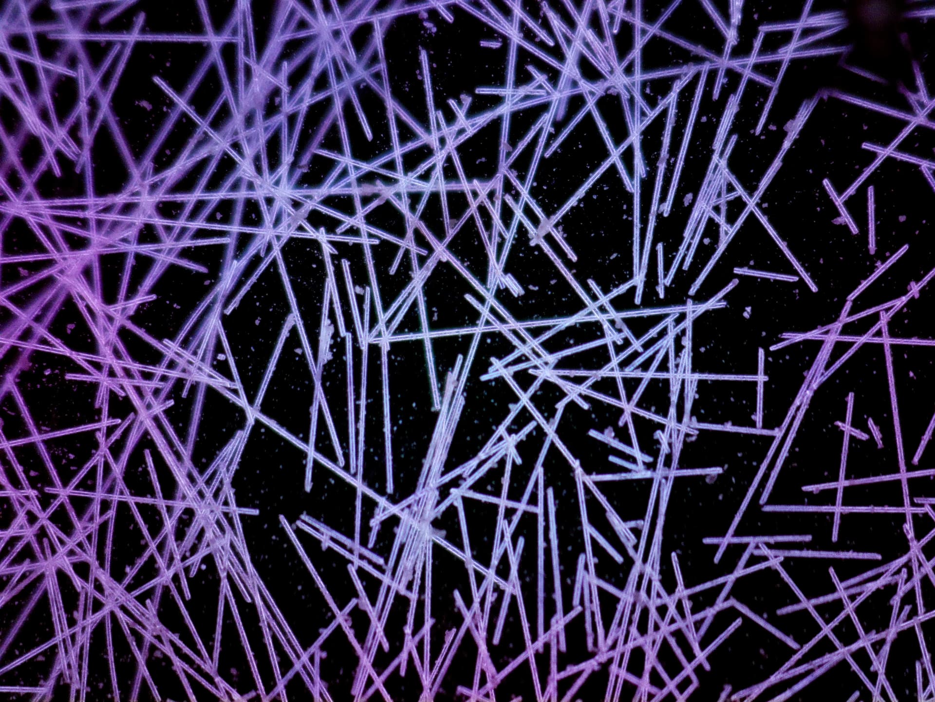
Given our translucent glass fibers, I decided to modify the illumination for darkfield, using a ring light ordered from Amazon. I am much more comfortable with CAD than I am with OpenSCAD, so I modeled the components to fit directly:

Now we are getting single images like this (this is pre white balance):
Given the field of view with the 4X objective, moving the XY stage around doesn’t gain a lot of view, but it does improve it a little bit. We then stitch the tiled images together and send it to a small Python program I wrote that uses a known image scale to allow users to draw lines over the individual glass fibers and get the measurements that way:

The circle on screen is randomly positioned to help ensure fibers are randomly selected for measurement. If an endpoint of a fiber is within the circle, it is measured. This helps limit measurement bias.
Going forward, we may try modifying the microscope main body to allow more travel and ensure that our longest fibers can be fully imaged, but for now this is a huge quality-of-life improvement over our old processes. Much applause and gratitude to the OFM team for developing such great, accessible hardware and software.