@Muralig1984 that is a nice build, you have found a particularly neat power supply for it.
I see you have opted for the V6 type of illumination module. Is that one that you had from a previous microscope, or is there something about it that works better or you?
Yes the nuts are turning within the trap.I attempted with half success, putting in two nuts one above the other (screwing the first nut thereby pulling it up,followed by inserting the next one.these two nuts rigidly stayed even after removing the screw.)This was possible for only one slot.
By default
Does the nuts once pulled by whatever means stay at the elevated position ?
If not, how to pull the nuts up when the main body is already sitting over the stand?
No I had ordered for the black PLA …which is on the way…so I had to use the older one…nothing particular about the older one. On the contrary ,I am more curious to try the new one.
Yes. It should be bedded tight into the trap and then stay there firmly. There is a nut_trap_test.stl that can be printed to check that these nut traps are working as expected.
Just to add another data point to the discussion, the nut traps on my stand work perfectly. The nuts slide into the base with a nice click and are pulled up into the trap as the M3 bolt is tightened. Really impressed!
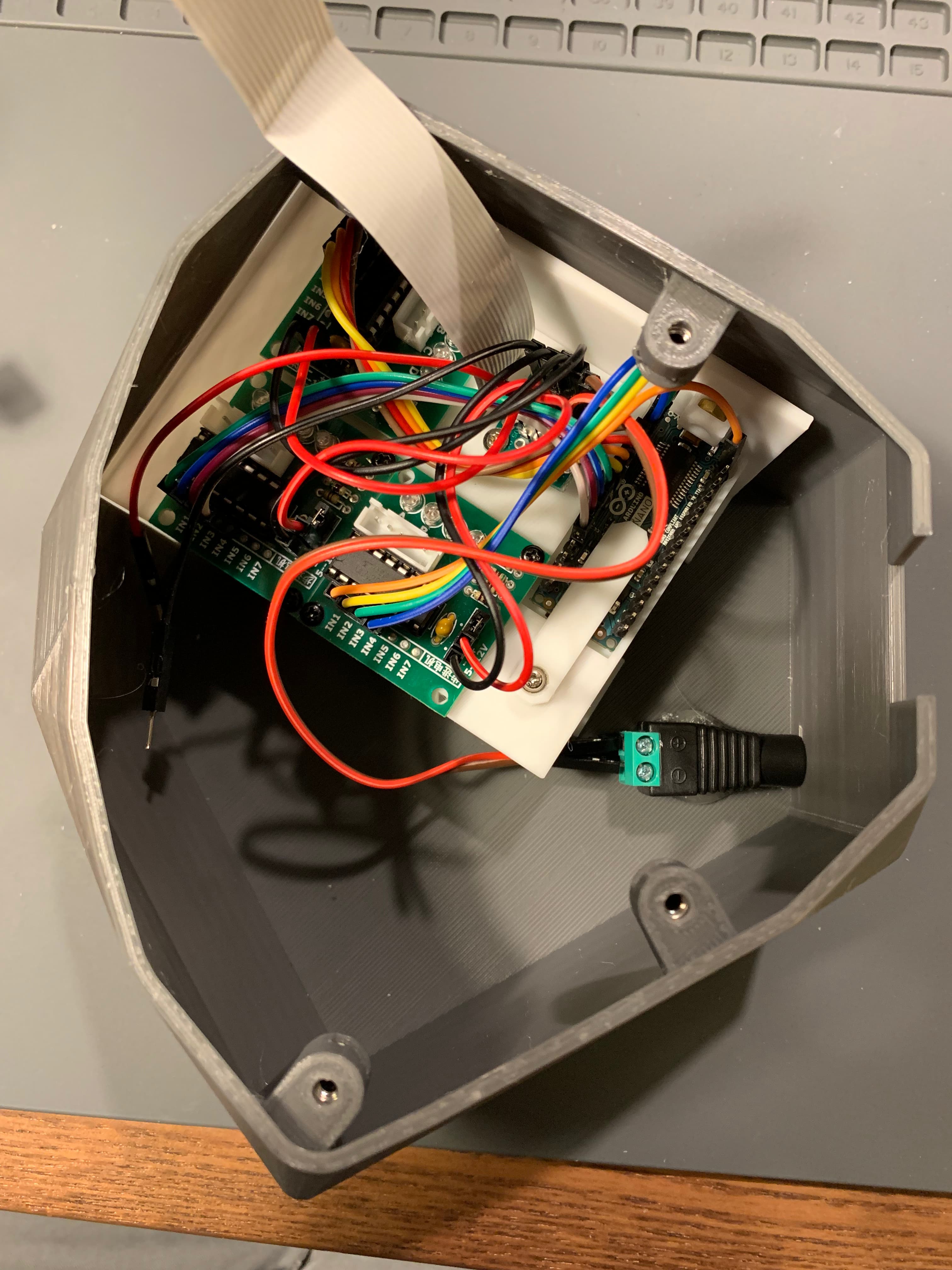
Hi all. I’ve nearly finished assembly of my v7. I’m having trouble with the pi cam ribbon reaching the pi. If using the tray and the nano converter plate is there a trick to getting a standard ribbon cable to reach or do I need an extension? Thanks.
The big sacrifice that was made for the v7-alpha base was that a 20cm ribbon cable is required instead of the 15cm one. I am embarrassed that this did not make it into the instructions yet. But I suppose this is why we do alphas. It will be fixed soon.
If anyone has a good idea for how to maintain both the benefits of the new base and keep with the standard ribbon cable I would be delighted.
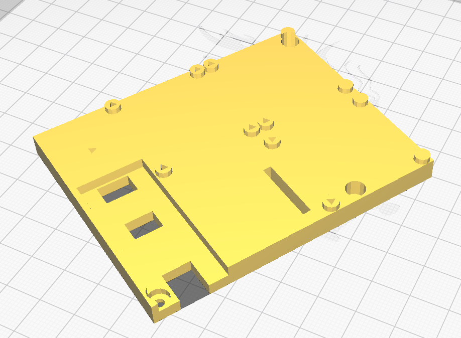
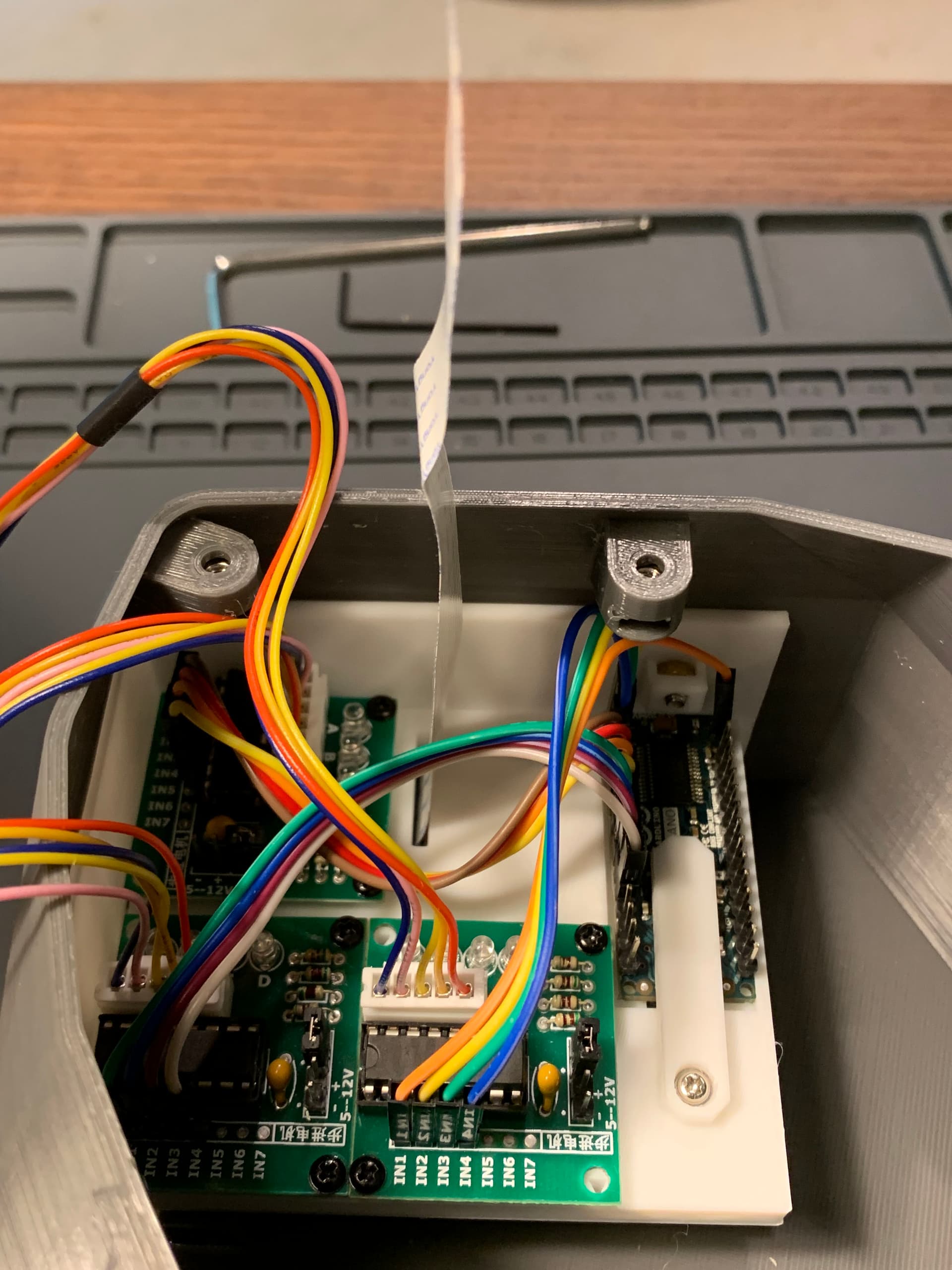
@j.stirling I’m not sure what future detrimental effects it might have as I haven’t used the microscope yet but as I didn’t have 20cm ribbon I modified the nano converter plate adding a slit directly above the pi camera input. The cable reaches now with plenty of slack. The slit can be made much thinner and moved over to allow another board in the bottom left square if required but that was just empty space for me.
I’ve now finished the structural build of my v7 and most of the wiring, just need to solder in the motor power supply. Should we continue to post any build issues here on this thread or do you prefer a separate thread for build reports?
Nice. I suppose when I meant that it didn’t fit I meant that you couldn’t remove the draw to reach the SD card without taking the microscope off the stand. We have a similar split in the Sangaboard v0.4. In fact if the slit reaches the side of the board then assembly is easier.
I am keen to be able to have an access draw to the electronics like this:
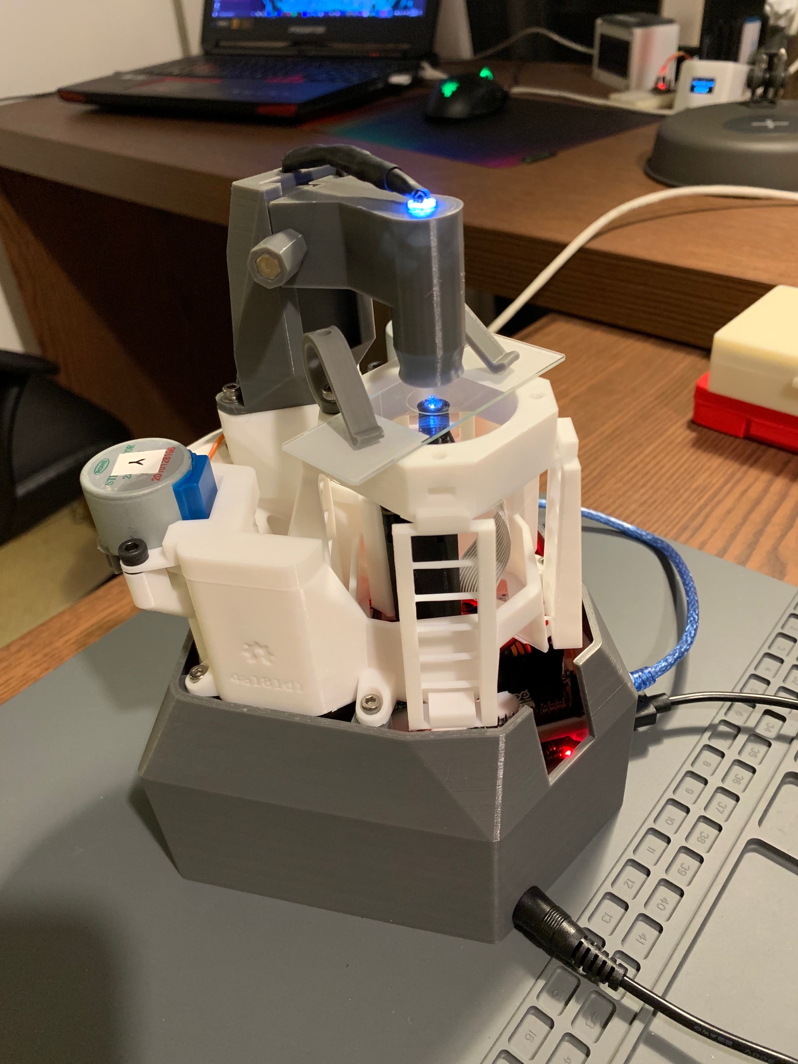
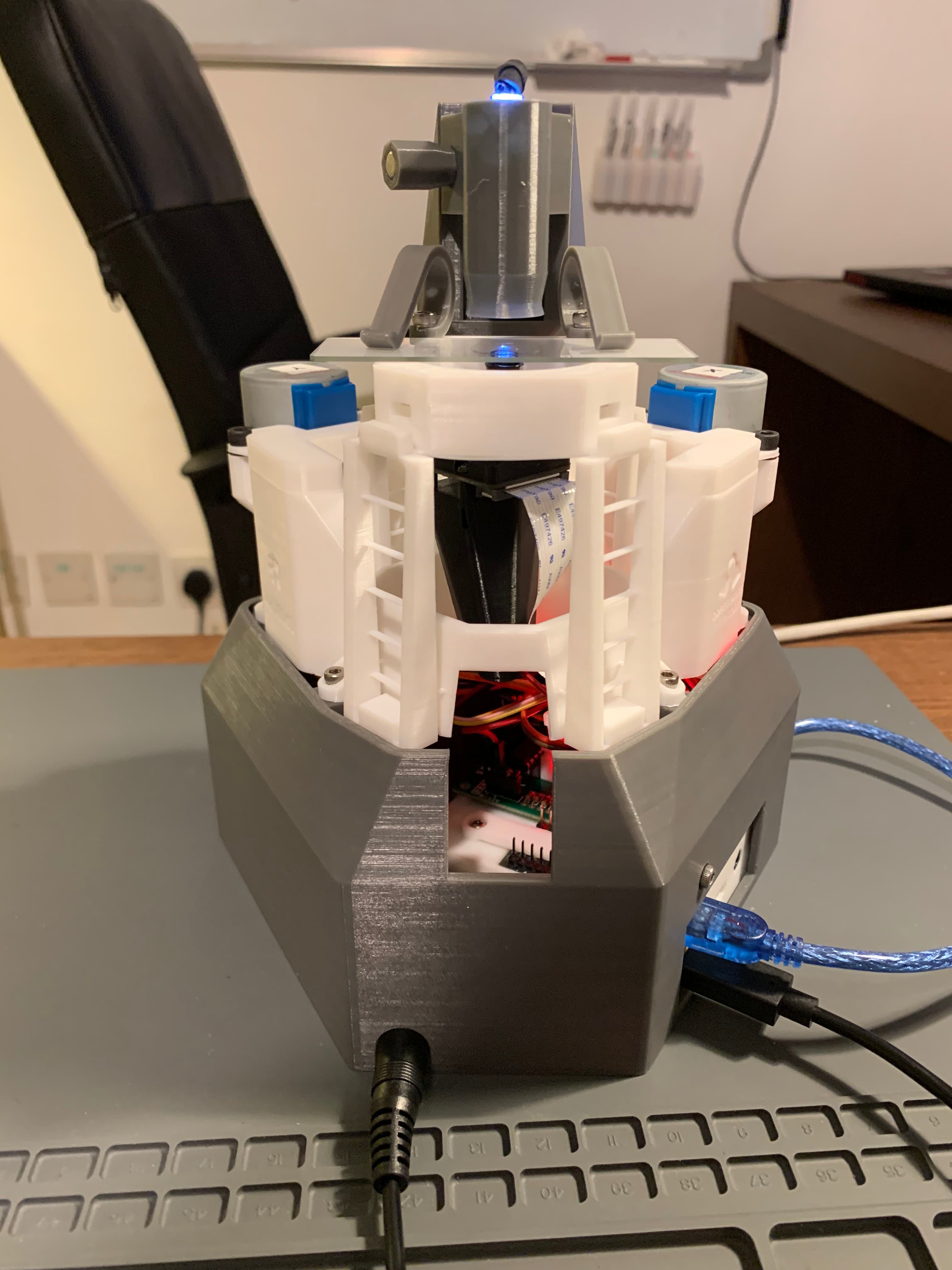
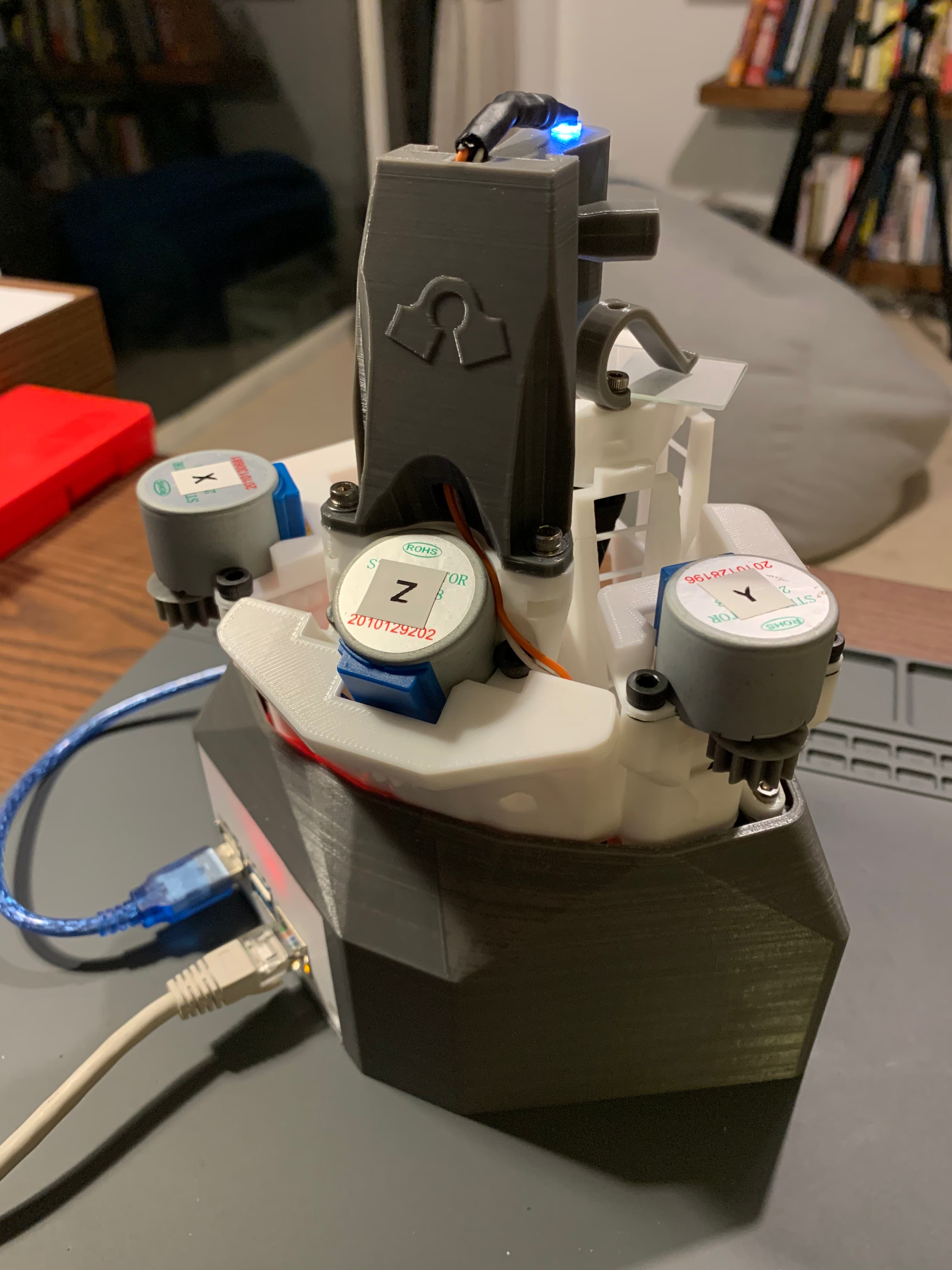
Hi all. I’ve just finished up my v7 build and thought I’d post my result and thoughts on here. Overall it’s an exciting update that looks and feels very professional and solid. Well done to all those involved in getting this update out!
The captive nuts work really nicely. Initially I didn’t tighten them enough and they fell out as it’s always a bit worrying tightening things in PLA. Once I torqued them a little further they stay locked in and none have come loose after multiple uses. I’m curious about the motor mounts. Is there any plan to give them captive nuts as one bolt in each motor spins freely for me in the PLA.
The electronics tray is great. I’m using a nano and the three motor driver boards and it all fits. As discussed above there needs to be a slot in the nano plate to allow a stock pi can ribbon to reach up to the camera. It’s a tight fit getting the tray in and out but I haven’t done a lot of work getting the cables tidied which would help a lot.
I like the cable tides, they make it very neat and smart. Not sure if I’m doing something wrong or if that’s what the slot is even for but there doesn’t seem to be a gap for the LED wires to go into the Z axis cable tidy. I just cut away the front edge to allow it to fit.
I modified the illumination dovetail with a slot to allow the LED wires to run down inside. I’m going to try again and have the exit slot closer to the cable tidy to completely hide the wires.
The new illumination setup is great. Easy to adjust with the thumbscrew and holds position.
I’m looking forward to seeing other v7 builds on here.
Nice colour scheme! Makes it look far more professional!
Also thank you for the kind words. As to your other points:
We had not planned to do captive nuts for the motor mounts. As we had not had many issues with them slipping. Just to confirm you are using M4 screws? We may have to revisit this, or perhaps suggest adding loctite.
Agreed.
Yes, sorry! The next alpha will contain illumination improvements including options to used an illumination circuit board, but also will include cable routing. I should have made a temporary hole in the cable tidy cap.
I still have not decided where I plan to run this cable. This is a nice option, does it affect the movement of the condenser.
All the build artefacts and STLs are in the link from the earlier post OpenFlexure Microscope v7.0.0-alpha1 released! - #8 by j.stirling
There is no specific Sangaboard case/tray. The sangaboard V0.4 will fit over the Pi in the pi_stand.stl. If you are using an Arduino Nano for the motor driver, there is a tray to fit that where the Sangaboard V0.4 is meant to go, nano_converter_plate.stl and nano_converter_plate_gripper.stl. You can see these as the white parts in the final picture in OpenFlexure Microscope v7.0.0-alpha1 released! - #28 by greenalastair .
Sangaboard v3 (which is the latest version we actually have) doesn’t yet have a mounting, largely because there’s only a few people who actually have them, so Julian prioritised the nano-plus-multiple-boards solution instead. We are hoping we’ll have v4 very soon, but they were delayed waiting on a particular transistor last time I checked.
@j.stirling the wire doesn’t interfere with the condenser so far.
Yes I’m using M4 bolts but I admit they are not particularly quality bolts. I might order some stainless ones see if it helps. When I first bolted the motors one of each of the bolts spun freely but the other bolt tightened. Now after taking the motors on and off a few times all the motor bolts are very loose and it’s causing the motors to rotate slightly as they run which is causing backlash. It may just be my print and hardware so interested to see if others have trouble.
That is a shame. I have found that they grip well, but a stripped thread there means a new body. The holes are long, and the recommended screws are short. You might be able to use a longer (15mm?) screw to catch further down the hole. It does not need to be button head, that is just to keep the tool count down as they take the same key as M3 cap head. Cap head M4 or pan head cross or slot should fit perfectly well.