Home / Limit switch

There has been some discussion about the need for a way to “know where you are” with the Openflex scanning stage. It was suggested that a home switch, indicating when the stage was at its center of motion, or close to it, would be better than a limit switch, indicating that the stage was at one extreme of its travel. I decided to try to develop such a thing. The general idea I’m showing would work for either an end-stop or a mid-scale home, but what I describe here is the latter.
I had been made aware, from work on another project, of the availability of cheap Hall-effect magnetic switches, which gave a binary output depending on the magnetic field around it (https://www.digikey.com/en/products/detail/diodes-incorporated/AH3377-SA-7/6124928). I also was aware of the existence of tiny rare-earth magnets; the ones I chose were 1/16” diameter x 1/32 thick (~1.6mm x 0.8mm) (MAGCRAFT® NSN0591 - Rare-Earth Disc Magnets). As part of this other project, I had designed a small PCB to hold the Hall sensor and a couple of passive components and some connectors. It seemed that could be the basis of some experiments with the idea.


The magnet is very hard to handle. I lost it several times. Scanning the floor with a strong refrigerator magnet always found it! You can see that the PCB is mainly full of connector pads. The actual electronics is only a few mm^2 in the center. I was able to remove most of the upper part of the board without breaking the connections to the chip, so that it could fit onto the microscope base (see later).
I first made a setup using some micrometer-driven translation stages, so I could assess the behaviour of the switch under the same conditions it would encounter on the microscope, i.e. with the magnet moving in the plane of the sensor, rather than perpendicular to it as it is intended to be used. The setup
is shown below. I connected the sensor output to an LED, so it would light up when the switch was activated. That way I could focus on the micrometer readings without having to look at a meter to know when the switch activated.
With this setup I could control the vertical and horizontal relative positions between the magnet and sensor, and also the spacing between the sensor and the magnet. The magnet and sensor are both glued to wooden blocks, to be sure there was no interference with the magnetic fields from the translation
stage components. The separation in the photo is about 0.5mm, which I felt was optimum, giving consistent actuation positions when translating the magnet.
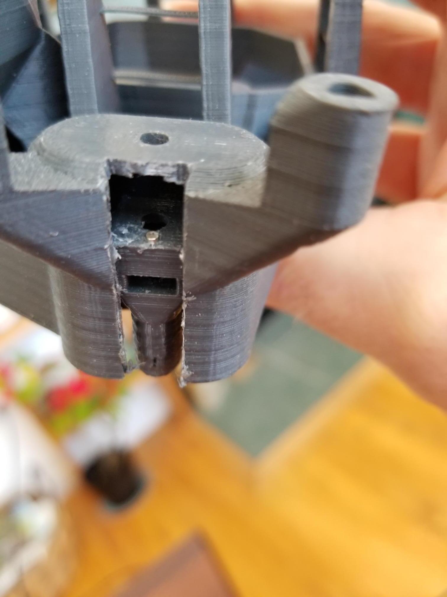
Having established that the scheme could work, the first decision was where to put the switch. The easiest place is on the actuator, because that only moves in one dimension, whereas the rest of the stage moves in two, making life very difficult for a switch. The actuator arm is hidden from view normally, so I first had to expose it. This is easily done by cutting through the plastic, which I did (carefully!) with a bandsaw.

Mounting the magnet was a two step job. In order to bring the magnet and sensor to the correct separation, since I couldn’t easily recess the sensor PCB, I had to pack up the magnet by about 1.5 mm. I used a small piece of aluminium sheet, and glued the magnet to that first. That made handling the magnet much easier. Before gluing the magnet, I had to make sure it was facing the right way since the sensor is only sensitive to fields in one direction. I established which way was correct by powering up the sensor and offering it up to the magnet, then flipping over the magnet until the switch activated. I
then marked that face of the magnet with a black marker for future reference. It was easy to glue the aluminium/magnet piece to the actuator in roughly the right position. A final design would make proper provision for holding the magnet in the actuator.

I then glued the chopped-down PCB to the actuator housing. Once I was satisfied that the switch operated correctly, I attached a step motor so I could record the axis position at the point of operation in a more precise way. Driving the motor using the Arduino commands in the terminal monitor proved convenient. I made several sets of measurements of actuation position. The positions varied by around +/- 50 steps, and had a hysteresis of around 2000 steps. I don’t know how much of the hysteresis is electronic and how much is mechanical. I always removed backlash by backing off a few thousand steps and then measuring the on-off transition in the direction which pushed the actuator against the O-ring spring; in my experience that is more reliable than relying on the spring tension to restore the actuator position, and should give more reproducible results.

If I understand the motor gearing correctly, 100 steps is around 6 microns at the actuator, 12 microns at the sample position. I believe that is adequate for this application.
If the community is interested in this setup then it could be easily “civilized”, by designing a custom PCB, and redesigning the actuator foot to hold the magnet, and the microscope body to accommodate the PCB in a well-defined position. I am happy to make the PCB, but I don’t know the CAD software
which everything is drawn in so I would need help getting that done. I would be happy to print such a redesigned instrument and check it out.
As I mentioned, a similar setup could work as an end-of-motion limit switch. The magnet could be embedded in the bottom of the actuator, and the PCB in the microscope foot. Is there interest in that version?

5 Likes

Hi @siddons this looks really nice! I think homing the stage to 12 microns is definitely sufficient for most of the things you’d want it for - ensuring you’re roughly in the centre of the travel range, or figuring out an automatic compensation for the non-planar motion of the XY stage. This ticks a lot of the boxes for me, but one feature I’d be keen to see is knowing, without having to search, which direction you need to move in to find “home”. Is that something that’s possible with a Hall effect sensor? So far I’d assumed it would only work with an optical sensor (using a flag that blocks the beam when you’re below home, and treating the dark-bright transition as the home position).

There was a previous implementation with microswitches in the foot, but we hit an annoying problem, which was that either we needed to put it high enough that it limited the travel, or it became too slow to reach the bottom of the travel and “home” the system. I wonder if this would be a nice replacement for that - because you could have the “home” position close to one end of the travel (which means you usually know which way to move to hit it) but without introducing a mechanical limit.

I think for what I’d like to use endstops for, knowing which direction to move in is fairly important - but I’d be keen to hear from others what kind of solution would work best.

I think there are two different functions that people might want. End indicators so you don’t go over range and break things. I don’t think you can do that without them being at the end, and are either end stops at the very end, or are close to the end with some directionality. The other is a fiducial mark, probably at centre. This is when you know basically where you are, but need a periodic check. You would search over a fairly small range of motion where you think it should be. If it is not within that range you have to go to an end or put an error flag.

Hi Richard,
My first approach was to implement a limit switch, but I was steered away from that. As I said in my note, it would be trivial to implement it as a limit switch. You would need to make a cylindrical cavity in the bottom of the actuator (what you see if you look at the bottom of the microscope) and make a recess in the foot to accommodate the small PCB with the switch. I have attached an stp file of a draft of the PCB so you can see what I’m talking about. I would need to do a test to find the actuation distance for this geometry, I’ll try to do so.The magnet is 1/16"diameter x 1/32 thick. I bought 200 for $12, so if you want a few to play with I’d be happy to send some. Take a look at the board, and if you think it might work I’ll get a few made. I have no clue how to edit the scad files to make any of that happen. It looks like a nightmare to me:))
Pete.

(Attachment home_switch.stp is missing)

Sorry, first time my attachment was rejected. “stp” instead of"step"!

Hi Richard,
My first approach was to implement a limit switch, but I was steered away from that. As I said in my note, it would be trivial to implement it as a limit switch. You would need to make a cylindrical cavity in the bottom of the actuator (what you see if you look at the bottom of the microscope) and make a recess in the foot to accommodate the small PCB with the switch. I have attached an stp file of a draft of the PCB so you can see what I’m talking about. I would need to do a test to find the actuation distance for this geometry, I’ll try to do so.The magnet is 1/16"diameter x 1/32 thick. I bought 200 for $12, so if you want a few to play with I’d be happy to send some. Take a look at the board, and if you think it might work I’ll get a few made. I have no clue how to edit the scad files to make any of that happen. It looks like a nightmare to me:))
Pete.

home_switch.step (190 KB)

Following the above discussion, I set up my XYZ micrometer stages to find out where one would need to mount the magnet and PCB to implement a limit switch. It seems the actuation distance for motion perpendicular to the PCB is 2 mm. If we want to put it into the microscope foot, the PCB would need to be buried in the foot so its top surface is flush with the existing foot surface (which currently acts as a hard stop for the motion), and the magnet should be embedded in the actuator by ~2 mm. Can that work?
Pete.

I thought about this some more, and decided to try to hack something up to see if a second limit switch could be added at the other end of the motion. I believe it could, if one could get access to the top of the actuator. I cut into the other (Y) axis on my sacrificial microscope base and discovered I could attach the small magnet to it quite easily (well, after a certain amount of fiddling to figure out how to actually put it there :slight_smile: ). See the picture below.20210221_141124|375x500

The top of the actuator enclosure is actually 2.2 mm thick, but luckily it gets thinner in the center, going down to around 2mm; just the spacing we need for the switch to actuate. The PCB I have for testing these ideas is a cut-down board for another project, so I can’t actually install it and demonstrate its functioning, but holding the board in place and moving the stage by hand it clearly does the job. Space is limited up there, so there will need to be a special PCB designed (not a big deal) and the large gear will need to be spaced off by adding a nut to the leadscrew, and the motor also spaced off by the same amount (maybe some washers).

Next, I’ll try to mock up the lower limit, although it will somewhat shorten the travel in that direction, since a proper job would need redesigning the foot to accommodate the PCB.

I know we all love the technology, but I was looking at my carved-up microscope body when I realized that the simplest way to see where the actuators are would be to cut a slot in the actuator (as I showed in my earlier posts) and add a pointer to the actuator which is visible from outside. Then you can know where you are just by looking? What is wrong with this picture?
Pete.

It is a nice solution to just look. But I have always found my self then having to think for a while as to which way I need to turn the gear to move towards the centre. It would be really nice for the microscope to just home itself.

I would worry about a slot in the actuator for strength, but I agree a clear physical pointer would be very helpful.

My usual method is to look in the slot where you insert the nut - when that lines up with the slot in the actuator, you can be sure the stage is centred. It’s a bit fiddly, but as Julian says I’d worry about strength if we cut a longer slot in the casing; it’s not that thick, and is a fairly important part of the microscope’s overall structure. I think it’s also quite helpful for keeping dust out of the mechanism - not an issue in a nice UK lab but definitely important for use in some of the more challenging environments where we find OFMs…

We could add a distance measurement tool in the foot of the microscope.
With that, we could know the rough distance (not extremely precise sensors) and thus distance but it would be quite expensive for a simple direction information.

A simpler solution would be to use the camera of the microscope directly and compute the position based on a calibration slide or block of which we know the exact position on the stage of the microscope.

Hi Richard,
As you have seen, I have hacked great slots in the actuator housing without any noticeable problem. Particularly when the feet are attached. The forces on the housing are primarily compressive along the screw axis because of the O ring; I can’t see where sideways forces would come from. OK, dust I can see being an issue, but nothing that a bit of Sellotape wouldn’t fix :slightly_smiling_face:

On another point: I’ve asked a couple of times if anyone can create solid models from the STL or SCAD files. I’ve tried everything I can find on the internet, but nothing gives be something I can edit in a normal CAD program. I want to modify the design to accommodate my limit switch design. It doesn’t need much, just cutting out space for the PCB at the top of the actuator housing, and extending the foot and cutting out the same thing there. Any suggestions (that don’t involve expensive software packages)?

Pete.

Hi @siddons, converting between OpenSCAD and [insert CAD package of your choice here] is a perennial issue, and one we’ve always struggled with. Unfortunately OpenSCAD will only export meshes, and while those meshes should be watertight it’s not straightforward to convert them to “solids” as understood by Inventor/SolidWorks/whatever. There is enthusiasm around porting a copy of the design to FreeCAD which would be able to export a solid, in a free package - but this is far from straightforward as the OFM is too complex for the current OpenSCAD toolkit to handle (at least, it was last time I tried). Since Julian’s big code cleanup, it is possible that this has changed.

If you’re able to import the STL as a mesh so you can position cut-outs in the right place, or if there’s a better way to specify where and how big the cutouts should be, I’ll happily generate a model with the required holes. I realise that’s not as helpful as supplying a ready-to-edit STEP file, but sadly that is something that’s proven very elusive.

The forces on the actuator shells are primarily compressive you’re right - the thing I worry about is twisting forces on the whole microscope body when the stage is not in its central position. Probably it would be fine, but I’m always reluctant to weaken the nominally rigid parts of the microscope.

Hi Richard,
I just spent some time going through the conversion process in freeCAD, using the procedure outlined in this link:

https://www.bantamtools.com/blog/convert-stl-to-step

It seems that freeCAD finds many errors in the microscope meshes, some of which it can fix, and some (folds seem to be the worst) which the fix causes chunks to be lost. If the file is fixable, this procedure works well. I was able to convert the leg-only file, and the pi-camera-pi-lens component, for example. The main base is not fixable. I attach a screenshot of freeCAD’s analysis, showing the errors. You can see that most of the problems seem to be related to circular or curved structures; I don’t know if they are bugs in openSCAD or what.
FreeCAD can also open openSCAD files in CSG format. I’d like to try that. openSCAD does not seem to be available for Ubuntu 18.04, which is what I run, so I can’t generate them myself. Can someone send me a CSG file of the main stage?
Pete.

Hi Pete,
the mesh errors are something Julian and I have periodically discussed - sometimes these are an artefact of ambiguous model construction (which you could blame either on our design or on OpenSCAD) but I could believe the OpenSCAD code isn’t perfect either. They are something we’re working to improve (e.g. Julian did a big tidy-up of a lot of my old OpenSCAD code, which should have helped at least a bit) but they are definitely not going to be completely eliminated in the short term.

I’m pretty sure I have obtained OpenSCAD on Ubuntu 18 under WSL, by adding a new PPA, there are instructions on how to add it.

I just tried to generate a CSG file of the main body. main_body.csg (632.7 KB) It generated suspiciously quickly (seconds) so I am not certain it worked and I’ve not yet checked it, but it’s worth looking to see if it loads in FreeCAD…

Hmm, the CSG file does look like it contains geometry - but FreeCAD 0.18 is not importing it for me (or at least it imports but then fails to render it)…

OK. Maybe it only works for simple shapes. In the meantime I have a working openSCAD, so I’ll see if I can figure out how to change it myself. I noticed that the latest design from git has new structures alongside the actuators. Are they for motor wiring?
I’m also interested in the delta stage, as it fits my needs better. Is there a publication describing it?

Hi Richard,
THanks for the file. On my installation it gives “Unsupported function: resize”, and shows a lot of components, none of which display as solids. So I guess we’re out of luck. Maybe freecad is just not up to the job. There was a comment on the forum about a commercial package working for stl->stp conversion, but I can’t see it now. I’ll search the forum a bit more later.
I should get the new PCBs for the limit switch today. I’ll send pictures when I have one assembled and tested.
Pete.

The latest design in Master on Gitlab has wiring channels from merge request !214 by @j.stirling. This does not fit on the old bases and there are some issues to be ironed out, such as #196.