Home / Limit switch

Great - I think the OpenSCAD import functions (and I think the CSG import is part of that) are not yet robust enough to handle a model with the complexity of the microscope. There was some interest from the FreeCAD community in figuring out how to do a port, possibly with a “summer of code” student, so we will see if there’s any chance of making progress there.

As William says, Master still has a few things that need ironing out before our next (major) release, so it’s fine to play with but I’d stick to 6.1.5 if you want a well tested release.

@samuelmcdermott is working on a publication of the delta stage, currently there’s nothing describing the microscope built around it other than the assembly instructions. It is used in the “OptiJ” paper that came out a couple of years ago, from the Sensors CDT in Cambridge, but they are just using it as a component in a larger system.

@siddons @r.w.bowman
In the few days or so preparing the delta stage for building, I always have to cleanup exported STLs with Netfabb. Not the best solution especially now that Autodesk own it but it is still the best for working with STLs and mold-making/3D Printing in general.
Netfabb also have rudimentary tools to modify per @siddons request so send the files my way if you need help.
Also wouldn’t it easier if you put the magnets in the blocks (between legs’ columns) and right-angle hall sensors on the inner wall?

Couldn’t homing be done cheaply via visual? Turn the motor a few steps (enough to negates backlash) then check if the image moved laterally? Likely moving upward since its a known distance. Can motors break the housing if we do this repeatedly?

It would be great if you could generate solid models (step files) of the mechanisms for the Openflexure microscope and the Delta stage, I can do the small changes needed for the switches given such a model. I already modified the foot, since freeCAD could generate the solid model. I will post a full description of the modifications in a few days. I think it came out pretty well and it is not expensive.

I don’t understand your comment about “homing vi visual”. Presumably what is needed is some way, which can be automated, to put the axes in the center of their motion. Can you explain a bit more what you had in mind?

Converting STLs to STPs is futile as it is basically upscaling. We also have to repeat the process for any new release. If you really need .stp then the effort is better used redrawing in other CAD or somehow modify the code so that Freecad can render it.

I mean we have a camera so it’s essentially an open-loop system. As long as we have a slide, the camera can see where’s the microscope move. Let’s say we move the slide XX micro to the right, the images we get should shift a certain expected pixels in the same direction. If we hit the end of travel then the images shift less or not at all. This way no endstops is needed.

@Hades_Corps that’s a potentially very interesting way of “homing” and one I have wondered about for a while, but never had time to try out. The current calibration procedure for the XY axes (which moves the axes and measures how far the image moves, to map pixels to motor steps) could be adapted (and sped up) to do this easily enough, I think - the tricky part is that often the system gets “sticky” before it hits a hard stop, and sometimes the hard stop it hits is not the top of the intended travel (which should harmlessly stop the motor from moving) but is the stage crashing into the objective. Also, once the motor has run out of torque tightening the screw, it may well get stuck and not be able to move back to the centre of its travel.

If we could reliably detect the microscope getting “slightly stuck” (i.e. moving a bit less far than it should) that might serve as a way to find the edge of its travel - but I’m not sure how repeatable it would be in the end. I think the only way to really figure out how well it would work is to try it - and I’d be excited if someone did this and it worked well. However, my gut feeling is that it would probably not be reliable enough to want to use regularly.

1 Like

This post describes the implementation of dual limit switches on the Openflexure microscope. This particular setup involved the Delta stage, but the actuator designs for both the Delta and the regular stage are very similar, so the information applies to both. In a previous post I described the general idea; to use a small magnet and a magnetic switch IC to make a compact switch which could be retrofitted to the microscope.
I designed a small PCB to hold the three components needed; the chip, a decoupling capacitor and a pullup resistor. The chip comes in an SOT32 package, and I used 0603 size surface mount passives. This is the smallest size I can hand-solder. The design was done using Kicad, and the PCBs were made in a few days by PCBway. I chose 0.5mm thick board, to minimize the depth of the cutouts needed. The boards as supplied were rafted 6 to a board (figure 1). They are easily broken off, but the best way to proceed is to assemble the components while the boards are still in one piece, since it is much easier to hold and work on. The individual boards are 4mm x 9mm, which is actually quite hard to work with. Figure 2 shows an assembled board, together with a micro-SD card for comparison. The Kicad files are on GitHub (GitHub - dpsiddons/limit_switch).


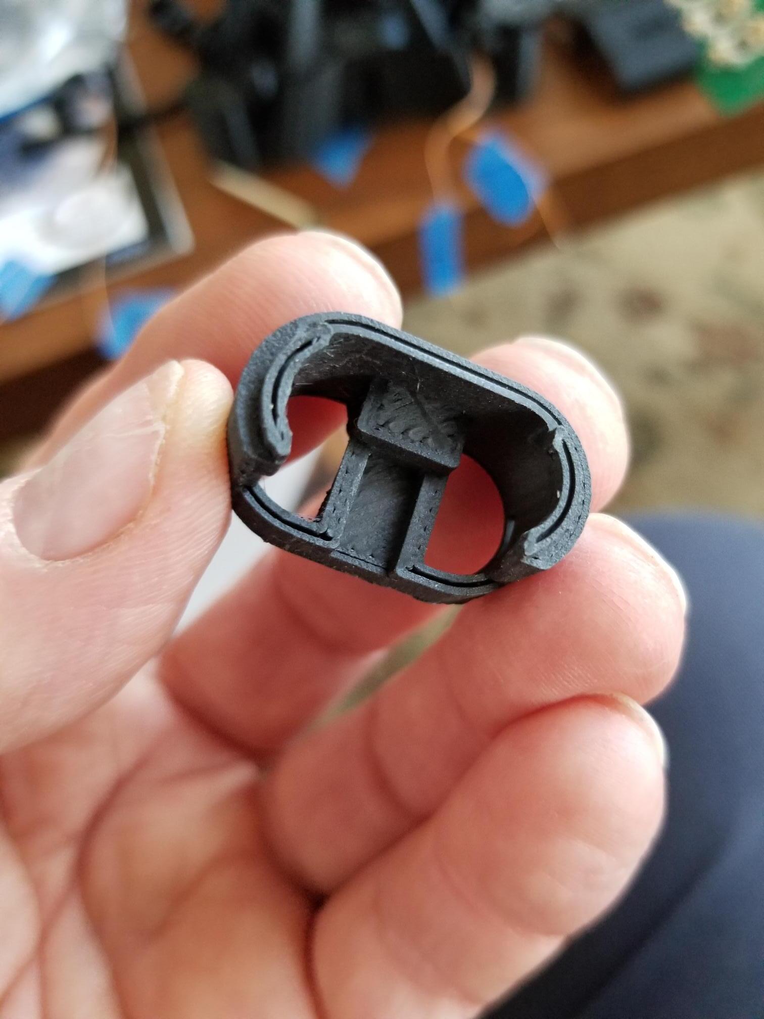
I still haven’t figured out how to modify the main stage SCAD file to accommodate the upper switch, so I hacked on the one I have to cut out a suitable cavity (figure 3). It fits nicely on the inside of the actuator housing, and as I’ll show, the lower one also works nicely facing inwards. That means all of the wiring is out of the way.

I had to think for a while before I came up with a simple procedure for installing the small magnets. They are exceedingly fiddly by themselves, so some kind of holder is needed to glue them to the actuator through the cutout. I eventually settled on the following. First, we need to discover which side of the magnet must face the sensor, since the sensor will only accept one polarity. To do that, I found a large magnet, such as is used to hold things onto refrigerator doors, and brought the sensor board near it, with the sensor facing the magnet, and the sensor powered up. I had rigged it up so it lit an LED when actuated. When the switch is actuated, you have the correct magnet face. Simply drop the small magnet onto this face and it will land right-side up. I then marked the small magnet with a Sharpie dot.
The magnet needs to be attached to the upper end of the actuator arm such that it aligns with the sensor on the PCB. It is easiest to do this with the arm raised to its upper limit, by pushing on the bottom. The arm translates when this is done without the actuator screw. Inserting the screw (without the nut) kept the actuator in the right place, but my screw was quite magnetic, so the small magnet preferred that to the actuator plastic! I replaced the screw with a matchstick and all was good. I guess one should print a suitable tool which would be a better fit than the matchstick, but……
To insert the small magnet onto the actuator, I put it onto a non-magnetic surface, good side up, took a matchstick and smeared the end with the thinnest layer of Vaseline. The magnet will stick to that quite readily (see figure 4). Next I prepared a small amount of Epoxy, and dipped the exposed face of the magnet into it, trying to avoid getting epoxy on the matchstick.


With your hand raising the actuator to its upper limit, insert the matchstick into the opening and press it into contact with the actuator head. The surface tension of the epoxy is greater than the adhesive strength of the vaseline joint so the magnet will stay behind when you remove the matchstick. Figure 5 shows the magnet installed.

Next, the PCB should be glued to the actuator housing, as in figure 6.


I initially just held it in place with my finger, and operated the actuator by hand to be sure the switch would be activated before the end of mechanical motion. Once sure of that, I glued it in place. Since this is still a prototype, I used Duco to hold it rather than epoxy, in case I had to remove it and readjust things.

The lower switch was made simpler by the fact that the foot was a simple (!) SCAD file, and I understood enough to make additional space below the endstop. I was then able to convert the foot STL file into a solid model using FreeCAD, and could then manipulate it using software I knew :slight_smile: I made a cutout to hold the PCB and bring the magnet and switch to about a 2mm gap near the end of travel. I knew this was the magic distance from previous experiments. I put in the endstop at the original height so we don’t break hinges if things go wrong. The modified foot (from the Delta stage, so it doesn’t have a tilted geometry) is shown in figure 7.


Next, glue the PCB into the cutout (figure 8). Again, I used Duco in case I needed to change things. The small magnet can be glued to the bottom of the foot in roughly the right place, in a similar manner to that used for the top limit. Ideally there should be a shallow cavity to properly locate it, both here and in the top of the actuator.

The axis can now be assembled with it’s ‘O’ ring as per the microscope instructions, and you’re ready to go (figure 9).

The next question is where to connect the 6 limit switch outputs. My motor setup at the moment is the simple one with separate drivers and a regular Arduino, so the analog inputs A0-A5 are available, and that is what the software expects us to use. None of the Sangaboards has connections for them. Modifying the Sangaboard .v2 to add a connector would be easy. Looking online, I see that the v2 was designed in Eagle CAD, which I don’t use, so I designed a simple board in KiCAD to hold an Arduino Nano, the two driver chips, and a connector for the switches, plus LEDs to tell when the switches are active. I haven’t made it yet, but will do so soon. I didn’t make any attempt to make it fit inside the microscope; maybe I’ll do so later.!
I then made some measurements of the repeatability of the end position. I ran the motor to the endstop, then backed away by a distance at which the switch turns off. The sensor has a significant hysteresis; about 5000 steps on the microscope, so I backed of 6000 steps, then moved forward by 10000 steps, ensuring that I would hit the limit. All of this was done using the serial monitor on the Arduino application, typing in commands. The results are shown below.
Upper switch:

Lower switch:

1 Like

It sound like there is plenty of work to be done on motion system first.
An alternative to centre would be using a pre-defined slide or disk with certain colour pattern.

I should clarify something: in the post I mentioned a hysteresis of 5000 steps. That hysteresis comes from the magnetic switch, not the microscope. Just like a mechanical microswitch there is a difference between the turn-on position and the turn-off position. That is desirable, since it prevents jitter, where some vibration or such causes the set point to be crossed. Having hysteresis guarantees that the first setpoint crossing will be latched, and only after a significant reverse motion will it be reset. This is NOT the same as backlash in the mechanics. Measuring that requires different instrumentation.

I recently came across an article from Texas Instruments describing a linear analog position encoder based on magnets and Hall-effect sensors which looks like it might work for the microscope ([https://www.ti.com/lit/pdf/slya051](https://www.ti.com/lit/pdf/slya051?keyMatch=LINEAR HALL SENSOR)). The sensors mentioned (DRV5055) are not too expensive (<$2). It seems a linear measurement range can be made with a range roughly equal to the length of the magnet. I found some 0.125" x 0.5" long rod magnets, also quite cheap ($10 for 30 magnets). I will dig into this a bit deeper and see if it is easy to adapt the microscope to use it.

1 Like

This is potentially pretty cool - if it means there’s a relatively simple way to add encoders to the axes, that would solve a lot of problems. The relatively slow speed means “homing” is annoying, but particularly for the delta stage, it would be very nice to know (even roughly) where the stage is. I guess you’d need to mount the magnet/sensor on the side of the actuator column, rather than the top/bottom? In many ways that probably makes it easier, I think…

I’m not sure why you think it is slow. The data sheet quotes 20kHz sensing bandwidth. Why would it be slow? The rate-limiting thing on the microscope is always the motors as far as I can see. My concern is how to calibrate it. As you can see from figure 2-3, the spacing of the magnet and sensor causes a slope change, so we’d have to be able to mount things in a repeatable, stable way, or dream up a simple calibration procedure.

1 Like

Sorry, I was unclear - I was referring to the motors being slow, not the sensor! The motors are indeed the rate-limiting step; that’s what makes homing annoying.

A calibration procedure that uses motor steps as a proxy for ground truth on actuator position ought to be simple enough to cook up - and it might be worth mounting the magnet on the horizontal actuator lever (or adding something to it) so that it’s not wobbled laterally by any parasitic motion of the vertical actuator column.

@siddons, I think @r.w.bowman was meaning the motors are slow, so a homing that needs to drive to a home or limit switch at the end of travel is slow and annoying. The sensor you suggest that can tell you where you are makes it much faster as there is less far to go.

For the slope changing with distance I think there are two things that would mean that is not too much of a problem. First I think the use case is mostly to find the mid-point or to avoid going past the end of travel. The midpoint does not depend on the slope, it is a zero-crossing - as long as the mid-point voltage is stable. Similarly the endpoint could be set to be the end of the sensing range, where the output does not change as the actuator moves. Second, the distance is probably reasonably stable in a microscope once it has been built, so a calibration routine would sort it out.

RIght. I misunderstood. You are right, most of the problems with limit switches go away if one has an absolute encoder such as this analog thing. What resolution do you think is needed to make it work in the way you outline?

Speaking of motors, are you aware of the simple mod to the motor to make it compatible with a bipolar driver? For example, https://ardufocus.com/howto/28byj-48-bipolar-hw-mod/ . There are a lot of bipolar drivers out there with some nice capabilities, which might provide higher speed than the simple unipolar driver. I don’t know numbers, but a constant-current drive with a higher voltage can certainly help.

Thanks - I’m aware of the unipolar-to-bipolar mod, but it’s just tricky enough that I think it would put a lot of people off building the microscope. It’s frustrating, because as you say there are a lot of very capable (and cheap!) driver boards for bipolar steppers. I don’t know whether better drive electronics (and bipolar drive) would help us go faster - it’s certainly possible, but I’m nervous about using the motors off-spec, particularly with a view to eventual medical certification in the future. My guess is you might get a factor of two, which is worth having but not earth-shattering.

I think William’s point is a good one: we already gain a lot just from having a three-state readout (above, below, or centered). That would allow you to home the microscope to a centre position, and to always know whether you are above or below (i.e. you would always know which direction to move in). The nice thing about that is that you wouldn’t need much precision - obviously it would be nice to have a repeatable zero crossing point, but being able to home it to the sort of precision you showed with the endstops is already helpful.

For an encoder, I think a resolution of anything up to 0.1 or 0.2mm would be enough to make a sensible feed-forward correction to planarise the motion (i.e. to calculate the transformation from XYZ to motor coordinates as a function of position, rather than using a global one). That should get rid of the trigonometric error, at least to some extent.

If we could do better (like 10um) that starts to get really helpful for e.g. checking we’ve not missed steps during a tile scan, or ensuring we’ve returned to the right place after a move.

Really detailed servocontrol for high-powered microscopy probably wants more like 100nm resolution, which I can’t imagine is feasible - but that’s fine, I think we can figure out ways to get the really fine detail from image analysis. In any case, that level of resolution is probably only helpful if it’s directly measured from the stage, rather than the actuators - I imagine we will notice some hysteresis in the plastic at that level!

Lastly, if I’ve read it correctly, the third sensor in the application note you linked to does 3-axis measurements; if you had one (or two) of those, could it measure the position of a magnet in 3D? If so, would a small magnet on the stage and a sensor board underneath it allow us to measure 3D position of the sample? That would be pretty cool, especially as it might let us directly measure and compensate for non-planarity in the mechanism. I guess it would be rather harder to make though, and require more complicated analysis…

1 Like

I think that would make an excellent student project, but it is beyond what I would have time to investigate. I don’t have ready access to students without funding, so it would be up to you :slightly_smiling_face:

Seriously, the field around a rod magnet is highly non-linear. Any mapping of 3-axis field to position would be complicated, and would probably work better in some directions than others. That could probably be mitigated by having multiple magnets and sensors, but that only increases the complexity. Having multiple magnets brings up the probability of cross-talk between them and the sensors.

I noticed that in early versions of the microscope all three axis used the same mechanism. Then you changed the Z axis to this tilted geometry. Can you explain what motivated that?

Hah, yes - I suspect you are absolutely right, it would most likely be horribly complicated. I’m not sure I’d want to supervise that project!

The move to the tilted Z axis came about largely as a way to make it stronger, and stick to the print bed better. The old version had all of the levers either horizontal or vertical, but involved a lot of floppy, thin beams:

image

I wanted the static part of the main body to extend underneath the Z axis strut - i.e. so that the static anchors for the X and Y axis levers are directly connected, rather than needing a gap for the Z axis at the bottom. That necessitated putting the lower strut for the Z axis higher than z=0. I wanted to keep the Z actuator on the print bed (to save faffing around with extra supports and release mechanisms), and consequently the beam that connects the Z axis actuator to the lower strut in the Z axis is not horizontal any more. In order to make sure the screw is pulling perpendicular to that lever, I needed to tilt it away from vertical.

Has anyone tried to detect stalling motors, e.g., using an accelerometer?

During homing every axis could then move towards its maximal position until the motor stalls and the frequency of the accelerometer data changes. I would imagine it to be similar to INPUT_SHAPER on Klipper 3D printers.

Homing would be rather slow but the accelerometer sensor only costs a few bugs and could just be attached to the microscope’s frame.

Any ideas why this is super silly or could work? :smile: