In an earlier posting (Home/limit switch) I described a system to provide limit switches (or end-stops) to the microscope mechanism. It was based on a pair of Hall-effect sensors and a small magnet embedded in either end of the actuator column. This then could be used as a home signal to reset the position scale after a power-down. This requires moving to the end of travel and setting the postion to zero. Given the fairly slow speed of the motion, that can be a time-consuming operation. Responses to that posting suggested that a preferable solution would be an absolute encoder, which did not lose its position on power-down. By chance, I came across a TI application note[https://www.ti.com/lit/pdf/slya051] for its Hall sensors which described just such a system. I have used the test setup I built for the end-stops measurements to explore this possibility. That setup uses the same motors as the microscope, so the Sangaboard firmware works. For this setup I get 8192 steps per mm. The data look really promising to me.
The system uses a TI sensor which provides an analog output voltage proportional to the applied magnetic field component perpendicular to its plane. The sensor is placed near a bar magnet such that it senses the field component perpendicular to the long axis of the magnet. In this geometry, when the sensor is at the mid-point of the magnet, this component is zero; the field lines are parallel to the magnet. Moving in either direction along the magnet length causes the field to increase either positive or negative, depending on the direction. Thus, the sensor output is a measure of position. The shape of the output voltage curve which results depends on the proximity of the sensor to the magnet. When it is close, the output is quite nonlinear, but if it is moved away a few millimeters, the central part becomes quite linear. In the following I will show the results of my measurements.
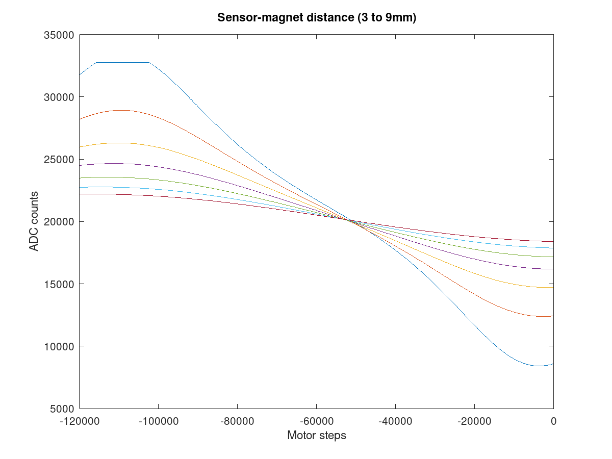
The first test was to look at the shape of the output curve versus distance from the magnet, to try and choose the optimum placement. The curve below shows the measurements.
The magnets I used were ½” long x 1/16” diameter [MAGCRAFT® NSN0578 - Rare-Earth Rod Magnets][ K&J Magnetics: D18]. The general rule is that close in, the field is stronger but the curve is non-linear for all the travel. Further away and the curve starts to show a linear region in the center of travel. This is the situation we want. It is then essentially a compromise between linearity and signal strength. I decided that around 6 mm separation was good.
The collection of the data was done using a Python script to move the steppers on my XYZ translation stage, with the output of the sensor being recorded by an ADS1115 analog-digital converter. I first tried using the Arduino’s on-board 12-bit ADC, but the resolution was marginal. The ADS1115 is a 4-channel 16-bit device, which gives much better data. It is readily available mounted on a small PCB; just google ADS1115 and a host of vendors will pop up. It is already supported by the Sangaboard firmware, masquerading as the light sensor. The sangaboard program needs to be configured for single-ended inputs. By default it assumes a differential input on channels 0 and 1. I also modified it to allow all 4 ADC channels to be read, by using the parameter already passed to the module, but not previously used. The chip is readily available on a small PCB which is easily hooked up to the Arduino [Assembly and Wiring | Adafruit 4-Channel ADC Breakouts | Adafruit Learning System]. The distance was changed in 1 mm steps, and the linearity scan consisted of 600 points, each 200 steps apart, covering a range of 14 mm.
The python script writes a series of files in Octave’s ASCII format. I use Octave (an open Matlab clone) for most of my computational work and find it very easy to use, particularly when dealing with large arrays of data. All of the plots here were generated using Octave.
The next step is to fit this thing to an actuator. I knew there would be trial and error involved, and I didn’t want to have to wait 24 hrs for a new microscope to print, so I hacked at the Openflexure’s SCAD code and generated a single actuator on a simple stand, so it could operate free-standing. That object only takes 4hrs to print.

The magnet is embedded in a hole in an addition to the actuator column. The housing had to be extended a couple of millimeters to accommodate that. The sensor PCB was glued to the outside of that extension. Again, a Python script was used to measure the response over the travel range of the axis. The result is shown below.

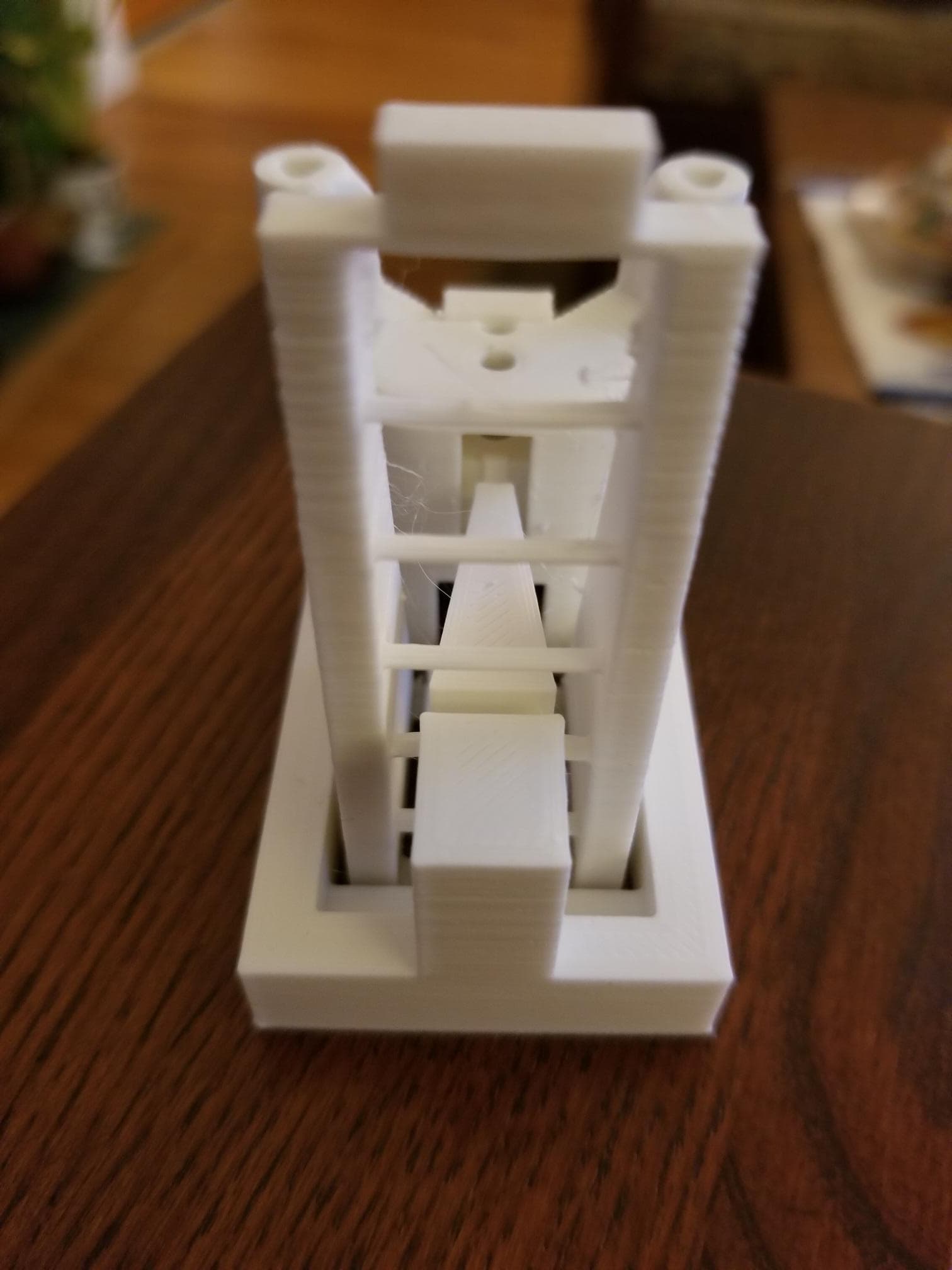
The graph shows the superposition of five consecutive scans. The system is very reproducible, including the oscillations at the lower end of the scan. I suspected that they may be the result of uncontrolled lateral translations of the column. A discussion with Richard suggested the addition of a stabilizing link from the microscope base to the top of the actuator column. This should be stiff for lateral motion but allow vertical motion. The photo below shows the stage with this addition. It adds a triangular strut with flexures at the base and tip such that it provides the required degrees of freedom.
The following graph shows the same scan as the previous graph. The reduction of ripples is obvious. The slope of the graph is reversed because I accidentally put the magnet into the column in the opposite polarity. The graph shows 10 consecutive scans plotted together and it is hard to see the differences; a good sign!

To bring out the differences, I fit one of them (#5) to a 5-segment spline and plotted the differences of all ten data sets against this fit. The result is in the plot below.

The peak deviations are around +/- 20 ADUs. It turns out that one ADU is approximately 1 um. If we could eliminate the once-per-turn errors, the remainder would be closer to +/- 5 um. I’ll keep looking for the source of this periodic error. Again, the reproducibility of the data is amazingly good.
So, the real test of all this is how useful will it be in a microscope? First, there will be no need to home the axes anymore. As soon as the instrument is turned on, you know exactly (well, +/- 20 um) where you are. It is difficult to see how any economically viable home switch could do better than that, and you don’t have to wait. I’m not a microscopist so I don’t have an intuition as to what makes a good instrument. I would hope that this helps.
In order to do the acid test I need to put my stage additions into the full microscope base. I struggled with SCAD to extract my little test piece from the full code, but putting it back is beyond me  I have attached my SCAD code which builds the bones of my test stand minus the additional support blocks. Is there a SCAD guru out there who would be interested in doing this?
Below is the SCAD code for the mods to the leg and actuator, ready to be put back into the microscope base. I would have attached a file, but the web site didn’t want me to do that::
use <…/libs/utilities.scad>
use <…/libs/compact_nut_seat.scad>
use <…/libs/logo.scad>
use <…/libs/z_axis.scad>
use <…/libs/wall.scad>
use <…/libs/main_body_transforms.scad>
use <…/libs/main_body_structure.scad>
//use <…/reflection_illuminator.scad>
use <…/libs/libdict.scad>
use <…/libs/microscope_parameters.scad> //All the geometric variables are now in here.
$fn = 32;
module prism(l, w, h){
polyhedron(
points=[[0,0,0], [l,0,0], [l,w,0], [0,w,0], [0,w,h], [l,w,h]],
faces=[[0,1,2,3],[5,4,3,2],[0,4,5,1],[0,3,4],[5,2,1]]
);
}
module housing(){
// front wall
difference(){
translate([-5,10,0]){
cube([10,2,30]);
}
//sensor slot
translate([-2.5,11,0]){
cube([5.0,1.5,30]);
}
}
//right wall
translate([-5,7,0]){
cube([2.5,4,30]);
}
//left wall
translate([2.5,7,0]){
cube([2.5,4,30]);
}
// top
translate([-5,8,30]){
cube([10,4,2]);
}
}
module housing_with_nut_hole(){
difference(){
housing();
translate([-4,6,18]){
cube([8,9,3]);
}
translate([-2,47,0]){
cube([4,1,30]);
}
}
}
module x_only_actuator(){
params = default_params();
ties = key_lookup(“print_ties”,params);
actuator_h = key_lookup(“actuator_h”, params);
translate([0,34,0]){
housing_with_nut_hole();
}
actuator(params);
translate_y(actuating_nut_r(params)){
            actuator_column(actuator_h, join_to_casing=ties);
    }
//actuator_column(actuator_h, join_to_casing=ties);
translate_y(actuating_nut_r(params)){
difference(){
xy_screw_seat(params, label="");
translate([-3,6,0]){
cube([6,2.5,30]);
}
}
}
flex_len = flex_dims().y + microscope_wall_t()/2;
w=flex_dims().x;
reflect_x(){
translate([leg_middle_w()/2-w, 0, lower_xy_flex_z()+0.5]){
//Each flexure is the hull of two offset cuboids.
hull(){
repeat([flex_len,-flex_len,0],2){
cube([w, tiny(), flex_dims().z]);
}
}
}
}
// magnet holder block
translate([-2,38,2.5]){
cube([4,5,15]);
}
}
module magnet_hole(){
difference(){
x_only_actuator();
translate([0,40,4]){
cylinder(h=38,d=3.5); //hole for magnet
}
translate([-3,25,16]){
cube([6,3,14]); // cutout for second actuator arm
}
}
}
magnet_hole();
CubePoints = [
[ -3, 0, 0 ], //0
[ 30, 4, 0 ], //1
[ 30, 6, 0 ], //2
[ -3, 10, 0 ], //3
[ -3, 0, 4 ], //4
[ 30, 4, 4 ], //5
[ 30, 6, 4 ], //6
[ -3, 10, 4 ]]; //7
CubeFaces = [
[0,1,2,3], // bottom
[4,5,1,0], // front
[7,6,5,4], // top
[5,6,2,1], // right
[6,7,3,2], // back
[7,4,0,3]]; // left
module wedge_arm(){
rotate([0,0,90]){
polyhedron( CubePoints, CubeFaces );
}
}
module wedge_arm_hinges(){
difference(){
translate([5,0,21.4]){
wedge_arm();
}
translate([-6,-3,21.8]){
cube([12,3,3.6]);
}
translate([-6,26,21.8]){
cube([12,3,3.6]);
}
}
}
wedge_arm_hinges();


