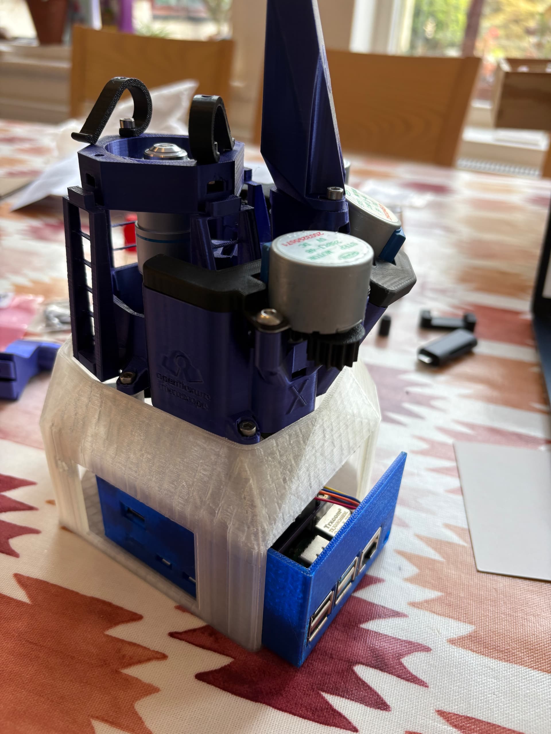
Started building the microscope today (UK based).
Bought kit from https://labcrafter.co.uk
Printed components in:
Black PLA, silk purple PLA, transparent PLA, and transparent blue PETG (for the pi case).
Built most of it in ~2hrs. Not fished yet. Tbc…
4 Likes
The finished build! 
Documentation was brilliantly written, really appreciate all the details and images to make the process easy to follow.
1 Like
Performed a 15 x 15 scan (1 z-step)
- 40x objective
- 2000 step size for x&y
- Autofocus fast
- Stitched images with openflexure-stitiching
3 Likes
High res image captured using V3 alpha server.
Any ideas why the red colour is at the periphery at the image? Any ideas how to fix this?
When setting up white balance the screen was uniformly grey as expected.
Was the previous stitched image scanned with the server v2? Then stitched afterwards?
The colour correction in v2 and v3 is different, because of the way in which the camera stream can be processed in the GPU for the different underlying Raspberry Pi operating systems. Your two sets of images reflect that change in overall colour balance / saturation. However both stitched images show more pink in the centre of each image, and a more washed-out colour around the edges.
The underlying cause of the washed out colours around the edges is in the construction of the Sony camera module on the Pi Camera v2. The sensor module is designed to work as a smartphone style camera with a short focal length lens close to the camera. The details of the consequences of this are in Flat-Field and Colour Correction for the Raspberry Pi Camera Module | Journal of Open Hardware (particularly fig 1 and 2). Overall it means that in the microscope images colours will be correct in the centre of the image, but there will be mixing of the colour channels around the edges of the image. In practice this is particularly noticeable for H&E stained slides, as you have.
It is possible to correct for this colour mixing, if it can be fully characterised for the optics module. In the paper that I linked there is detail of measuring the mixing, and the results of applying an unmixing algorithm. None of that is available in v2 or v3 of the OpenFlexure software. @j.stirling has done some development of an implementation of a generic colour correction - using the specific colour mixing measured in the paper for that particular Pi Camera v2 to apply to all microscopes with a Pi Camera v2. This is in a repository on the OpenFlexure GitLab: OpenFlexure / OpenFlexure Colour Correction · GitLab. At present it is a work in progress without a polished interface. It needs to be run manually on a set of images taken in a scan, then the stitching applied afterwards. It does make a significant improvement in the colour fidelity across the images, without every microscope user needing to characterise their colour mixing.
1 Like
Colour correction is high up on our agenda for the alpha 3. Working out the exact method for the colour correction is a bit tough as we cannot do it within the GPU pipeline as we effectively need a different colour correction matrix depending on the location in the image.
Post processing the images requires us to back out the non-linearities of the gamma correction.
Images should also be much more uniform once we get a version with the HQ camera, but that is some way away.
1 Like
Thank you both for your very quick and detailed replies.
Yes, that is correct the first scan was with server v2 then stitched afterwards and the second was with v3 alpha and stitched during the scan.
I tried using the openflexure-colour-correction but was getting an error. I’m more of an R user than python user (tbh  ) so not sure what’s going on here (see attached).
We’re looking to use this microscope in Uganda for cancer diagnosis, my dad is a retired histopathologist and has set up a charity (https://africacanceraction.org) and I help with some programming. We’re looking into modifying the microscope for our specific use case but sounds like you already have that in the works with the HQ camera. The next trip to Uganda is a few months away but would love to get the OFM over there working in the lab on the next trip. For time being would you recommend a more manually process of scan → colour correct → stitch. I’d also like to develop an extension or web app to help easily share the scans with colleagues around the world to give second opinions but this is very early days.
Thanks for all your hard work on this, it’s a very exciting project!
1 Like
Hi @Rosie231,
This is great work we would love to follow up with you directly and make sure that OpenFlexure can support the fantastic work that you and your father are doing.
Depending on where the bottleneck is in what you want to do, if you have time on the microscope it may be worth increasing the overlap percentage to minimise colour effects rather than directly correcting.
As for the extension for directly sharing scans, have you seen our image viewer? We need to work out a good way to create an upload interface, and a way to either cover hosting costs/administation; and/or a way to make it easy for others to host their own. We would be really interested in your feedback as to what would be needed to support the work you are doing!
Yes, this is really exciting! I’m late to the party so Julian and William have said everything there is to say, really - but I will be very keen to keep engaged with what you’re doing. Colour correction is something we started working on years ago, but I think we’ve finally hit the point where it’s now at the top of our list for going into the software.
Thank you for all your replies to Rosie.
I’m looking at this microscope to see if it is suitable for diagnostic purposes in routine Histopathology, and if scanned images can be emailed for second opinions, et cetera.
As noted before we assembled this with the high resolution optics using an unbranded x40 objective of NA 0.65 with the recommended tube lens from LabCrafter. I am very impressed by the flatness of the field – right out to the periphery of the image - with this lens. I have also tried a Zeiss PlanApo X10 - surprisingly, this is definitely out of focus around the edges.
I’ve carried out a few measurements using eyepiece micrometers: the field diagonal of the image is 0.46 mm. Which is pretty close to the 0.45 diameter that would be observed in a conventional microscope with a X 10 eyepiece with an 18 mm field. Most microscope cameras will only show a much smaller field so this is really impressive particularly as the field remains flat right out to the edges of the image. However the limitations for diagnostic Histopathology from H&E stained paraffin sections are the uneven colour balance and the lack of a low power image- hopefully solved with the stitching. Given that maximum resolution obtainable from a lens of NA 0.65 is about 500nm - i.e. aprox 740 X 540 pixels (monochrome) in the field avaible; has anyone considered using a sensor with a lower pixel count and less troublesome collimation , I note the comment on the HQ camera but the global shutter camera may be a better fit.
PS the imager viewer is great.
micrometer spacing 2 microns
2 Likes
Histopathology is a key current application focus for the core development team, and those issues are ones that we are trying to address. The colour balance in particular is unfortunately worst for H&E stained histopath sections. Cervical smears, blood smears and plants look much better. Much of our initial development was targeted towards malaria diagnosis, so we have only come hard against the problem more recently.
The plan is to spend a little more time trying to get unmixing working on the lighter, lower cost Pi Camera 2. If it seems to be intractable we shall move support for other cameras forward in the development path so that we can use the HQ camera.
The software is the limiting step here, and once we can add a second camera type, it should open up adding any version of a Pi camera reasonably easily. We already have a draft of the hardware for the HQ camera (and Pi camera Module 3).
[The HQ camera optics module is in GitLab mergevrequest !385. There are no instructions there, but you can get the STL part from the download artifacts button in the merge pipeline section. The build:archive artifact is a zip with the STLs in a folder docs/models.]
Colour correction is the top of our priorities, I have spent some time on it today. We had a version that was somewhat working but had issues due to non-lineiarity as it was applied based on gamma. There are still some issues but we are making progress see before and after:
Before
After
This results in stitched images that look a fair bit better.
Before
After
I need to do a bit more digging, but I think that perhaps having the same movement in x and Y will also help improve this.
1 Like
Some updates to colour correction can be found here where Joe has started using an HQ camera.