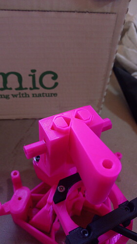
Feedback wanted! Experimental new illumination mount

I Would forgo the keyhole for the illumination if we go this route as it is not going to be hard to attach as it is outside the body. I am still not convinced this is a nice way to do the adjustment for the illumination. As once it is loose it will slip and you cannot hold the bolt with your fingers. I can imagine keeping the Allen key in as you try to adjust is going to be tricky.

Most of the design work on the "double dove was to make something that holds in place when fairly loose so you can slide up and down safely by hand until you are ready to lock.

My thinking on the optics/illumination mounting has evolved through a few versions. They have not yet been the same, so Iā€™ll summarise for each below in case itā€™s helpful.

optics module

first version (v5.12 or something)

This used a smaller version of the dovetail thatā€™s currently on the illumination. The optics module push-fit into the body. The ā€œarmsā€ were part of the body. This worked, and made it easy to assemble and coarse-adjust the focus. However, it went slack over time and if you abused it, you broke the main body.

I donā€™t think I ever swapped the dovetail round (so the breakable arms were on the optics module) but that might have solved one of the issues with it).

second version (later in the v5 series)

I swapped to using something similar to the current version, but with the concave part on the optics module. The slot didnā€™t have the ā€œkeyholeā€ opening, so the screw had to be inserted through the Z axis mechanism. This was really ropey! This coincided with the new Z axis design.

The bolted mount meant it didnā€™t go slack over time, and the shape self-centred and stayed aligned. Early versions had the ā€œnoseā€ of the convex part too pointy, so it didnā€™t self-centre properly and could wobble, later versions fixed that. Main disadvantage: it was a pig to assemble.

third version (same as v6)

I then made a few smaller changes:

  • swapped the convex and concave parts, so the optics module was convex. This gave slightly more space for components in the optics module, and a slightly greater area in contact with the print bed at the base of the mount, on the main body side.
  • used a ā€œkeyholeā€ shaped slot, so that the screw could be loosely inserted before the optics module was in place, then just tightened up in situ. This made assembly way easier.

My remaining gripes with the optics module mount are:

  • access to the mounting screw is still a pain
  • the keyhole slot has a limited Z adjustment range, so itā€™s not super customisable
  • it canā€™t be slid slightly - itā€™s either locked or loose

illumination

The previous illumination was a wobbly monstrosity, and I wonā€™t detail it much! Suffice to say it fitted onto the now-obsolete dovetail between the thin legs at the ā€œfrontā€ of the microscope (opposite the Z adjuster) and was very, very, very wobbly.

The new illumination was pinched from a hacked-together inspection microscope, which is why itā€™s so chunky. It could definitely be narrower than it is and still work fine. I like that it feels solid but can still be adjusted (some folk will move it up and down more than others), but I would prefer it to be lockable with a screw.

@j.stirling I totally agree, with the illumination itā€™s essential to be able to slide it without it being floppy. However, it would also be nice to be able to add/remove mounts without emptying the dovetail (e.g. a polariser)

Iā€™m really sorry but I am stopping for the day because the baby woke up! I ave more to sayā€¦

1 Like

No problem this gives me more to think about. It is true that having to remove everything to add the polariser is not ok! I will have to give this some thought!

Well adjusting four screws to centre in x-y is twice as many as currently, and itā€™s already pretty fiddly to get it in the correct place. If every time a user needs to adjust the z-position they will also need to adjust the x-y position it will be frustrating.

It should home to the same place though as the relative stiffnesses of the flexures wonā€™t change. It would be nice to have more control over the x-y adjustment than the slip plate, but that is a lot of engineering.

1 Like

I picked my microscope up just now and the illumination slid right down.

In case itā€™s helpful, my thinking on this is that there are a bunch of desirable features in an optics mount rail, and the right answer probably works nicely for both the condenser and the optics module. Iā€™ve tried to outline the goals below - perhaps it would be sensible to turn this into a wiki-style post so we can update these as the discussion evolves? Iā€™ve thought about this a lot but this is the first time Iā€™ve written it down, so sorry if it comes out a little garbled!

  • Self-centering: I think one of the most important features is that all the optics are close to being aligned in X and Y (transverse to the rail) without too much additional tweaking.
  • Friction-locking: Itā€™s important to be able to gently slide along the rail, and for it to hold its position even when the screw is loose (but not so strongly that itā€™s a pain to slideā€¦)
  • Lockable with a screw: once in the right place, we need to be able to securely lock it in position. Plastic springs are never going to cut it on their own, as weā€™ve seen.
  • Separable XY and Z adjustment: itā€™s much easier to align if you can move it laterally without moving axially, and vice versa. Bonus: separable X and Y adjustment. XY adjustment could be built in to the carriage or into the mount for the upper dovetail (as we do at present), I suspect itā€™s not easy or helpful to combine the adjustment into the dovetail mount as it adds complexity and makes it hard to separate the axes.

Some more features are probably not essential but would be really nice

  • Single screw to lock motion in Z (this makes it way easier to adjust)
  • Minimal motion when locking it (i.e. you can get it lined up, then lock it without it moving further)
  • Ability to add/remove carriages without sliding all the way to the end of the rail (helpful for modular/configurable imaging set-ups)
  • Breakable parts can be replaced without re-printing everything (probably this means integrating them onto the carriage, though sometimes it is more annoying to re-mount the optics than re-print the dovetail, so Iā€™m on the fence on this oneā€¦

After putting together the design I posted above, I concluded that a better version might simply be the existing dovetail, with a locking screw (i.e. something to pinch the two arms together). If done well, this ought to be robust and repeatable, and tick most if not all the boxes above. Iā€™ve no objection to making the dovetail a bit narrower than the present one.

The one major disadvantage of the present design that this inherits is that it doesnā€™t work well for short (<20mm or so) dovetails, as it is very easy to twist it relative to the rail. Itā€™s also a bit bulky, but at least for the condenser thatā€™s not currently an issue. Some trial and error will be needed to get the stiffness of the clamping arm right, and the pinch bolt should be as close to the dovetail as possible, to minimise unnecessary stress on the clamping arm. Arranging it so the flexure is rotated 90 degrees (i.e. horizontal, as Iā€™ve drawn it) means any clamping force would be along the axis of the flexure, where itā€™s strongest - probably better than what Iā€™ve put in the sketch, though I suspect it would be OK as Iā€™ve drawn it.

Not sure a wiki really helps as then we end up with non-chronological discussions which are worse to follow than long ones. Also I think everything bulleted in the top list is pretty much agreed on. I think the second list is also largely agreed on, though the relative annoyance of some of them may be up for discussion. Which is important as there will always be a compromise.

I suppose my initial video showed the evolution of the new structure but not exactly where I started. Plan 1 was to put a pinch bolt all the way across the current one. I do have one with a long M3 screw and two holes drilled in the current condenser ā€œarmsā€. I found it is still a reasonable amount of force to stop it moving and unless you do it up quite tight a knock can still totally dislodge the illumination.

I did consider the deepening the dovetails so it cannot snap on and off at the front, but then I decided it would be least likely to come out if the ā€œinternalā€ dovetail was on the condenser itself. But then I struggle with how to tension it. Which is how I evolved to the new idea.

I think the idea you have above could work but would only be robust with a deeper dovetail. Which would probably preclude being able to remove carriages without taking everything off.

I think we probably need to build 2-3 prototypes and put the on actual microscopes and try to use them to align the optics. Then iterate on feedback. I think we are past the point of sophistication that a sketch will tell us what works best in practice.

Fair enough. Couldnā€™t agree more re: testing vs sketching.

I think it might be worth clarifying what we mean by ā€œrobustā€. Ultimately, the microscope is a sensitive optical instrument - if it gets enough of a bash to knock the dovetail off, even the current one with a pinch bolt, chances are something will be out of alignment. If we make the condenser attachment rigid enough that it survives a serious knock, my hunch would be that it might then mean something more irritating gets knocked (or snapped). I think Iā€™d be happy with something that doesnā€™t slide down if you subject the microscope to vibrations; if someone is routinely bashing it, or squashing it in a badly designed case, itā€™s going to take more than an improved dovetail to keep it in alignmentā€¦

OK, so Iā€™ve printed the new illumination setup, because a) I got my condenser lenses in the mail and b) I wanted to experiment with filters.

However, it ended in frustration, and Iā€™m back to the standard setup.

The problem is that the double dovetail design is just terrible to adjust ā€“ due to the layer lines and the little bit of twist when the screws are loose, it is very jumpy. It also moves in X/Y when tightening, and this all resulted in me cussing wildly.

Another issue is that there is no room for the filter holder below the condenser part, but that may be just me absolutely not knowing where the right vertical placement for the condenser is ā€“ I assumed the focal plane (i.e. 5mm from the lens) wants to be about where the slide is, and with the filter holder in, the lowest-most position of the lens is some 15mm from the slide.

I think one solution would be to orient the parts (condenser and mount) on the printer so the layer lines are perpendicular to each other, so the sawtooth jumpyness goes away.

A better solution, however, seeing how fiddly it is to adjust in all 3 axes, would be to have a screw-driven adjustment system ā€“ maybe something with flexures?

regards,

christian.

1 Like

Thanks for the honest assessment, probably best to abandon this line of approach!

I learned a lot in the design of the part about what fixes well, but I think I lost focus on the final requirements. Concentrating on how to make the design work rather than on whether it was the right solution for the optics. Then fell into the trap of falling in love with the design when the bit I wanted to work did.

As for the point on the orientation of the layers in the dovetail. That will be a problem for both this design and Richardā€™s one. And it does get much worse as we start to clamp. However other orientations make it hard to print other parts of the structures.

I did do some sketches of screw driven translation. But screw driven dovetail translation is hampered by the quality of the print surface. And to get the displacement needed I worry the flexures would have to be huge and floppy.

I think this comes down to ā€œreasonable misuseā€. In a lab setting it will likely get a clunk or two in its lifetime, for example if someone carelessly reaching for something in a rush. As the condenser is the very top of the microscope it is in a more exposed position. If an accidental clunk causes misalignment this is unfortunate, but probably unavoidable. If the clunk takes the condenser off it could damage the lens (cheap lens-probably fine) but also dislodge the wiring down inside the housing while things are powered up. This is potentially a bigger problem.

I donā€™t think we can just dismiss the problem that a clunk dislodges the condenser. I think we must either:

  • Attempt to find a solution so it does not come dislodged, or decide that dislodging is preferable to other damage that could happen.
  • If we either canā€™t stop the condenser becoming dislodged then we need to think about how we prevent further damage if it is. For example better cable management with strain relief.

Thatā€™s a good point. I guess I was thinking you wanted the system to be unaffected by a knock (which I donā€™t think is realistic) but we definitely would want it to be un-broken. Better cable management is needed in any case, I think, but if we can arrange it so that a ā€œreasonableā€ knock wonā€™t send the condenser flying or scratch the lens, that does feel like the right answer. I think printing a few dovetails with different sizes might help us find something that is both easy enough to remove, but tough enough to take reasonable abuse.

Agreed. I was also thinking that if we decide that a clip over dovetail that can be removed is always too loose we can have multiple dovetails on the rail and a way to bolt thin optics into them. For example:

I know it is a different style of dovetail, it is just a quick sketch about how we might handle thin optics. We could probably shape the tongue and grove to give a more repeatable mounting.

Sure - I strongly suspect we can come up with something that is strong enough but also removable; I am curious why you are keen on making sure the female part of the dovetail is on the rail? Every optics rail system Iā€™ve seen does it the other way around (male dovetail on the rail, and sliders that clamp over it), and that certainly does make it easier to make a removable clamp. Iā€™m sure you have a good reason for that decision, Iā€™m just not sure what it is. I guess maybe having the male dovetail on the slider minimises the size of the slider?

For this part it was because it was easier to draw and was never going to be used. Or more because I drew ā€œa dove tailā€ without thinking, and saw no need to redraw it.

Before it was because I was worried about strength of the thin bits at the side. It is easier to make the mount chunky and wide than the slider. I did also at one point condenser that if it is male we can try to run the cabling down through the male dovetail. However I think this probably just alters where the problem is rather than fixing it!

Well, I have finally collected my print of @j.stirling illumination mount from our printer.

I think the layer-by-layer movement is less than the range of best focus of the plastic condenser lens, so it is not too bad. This is the same on the normal condenser mount anyway. Actually I find it tactile and satisfying to go in 0.2mm steps.

Doing the screws up did not really move it much. Certainly less than the slip mount for the xy position.

Being able to have the sample clips on the same side as the condenser is brilliant. I can get slides in and out now.

Printing little lugs that house the M3x25 hex heads makes it tool free.

Thinking about how something like a lathe works. You have a which is used to provide a smooth and adjustable bearing surface. If you split the male dovetail into two parts and the female into 3 you can print the dovetail itself and the gibs such that the bearing surface was on the print bed and was much smoother.


You are still running a smooth piece over a rough piece. If we think about it we should be able to make one of the gibs adjustable so the we can fix how tight the stage is. We can also probably make it so we can remove one side to get the dovetail off. The downside is more parts, more assembly, and the dovetail will need to be much bigger. Not sure it is worth the hassle, but worth thinking about.

1 Like