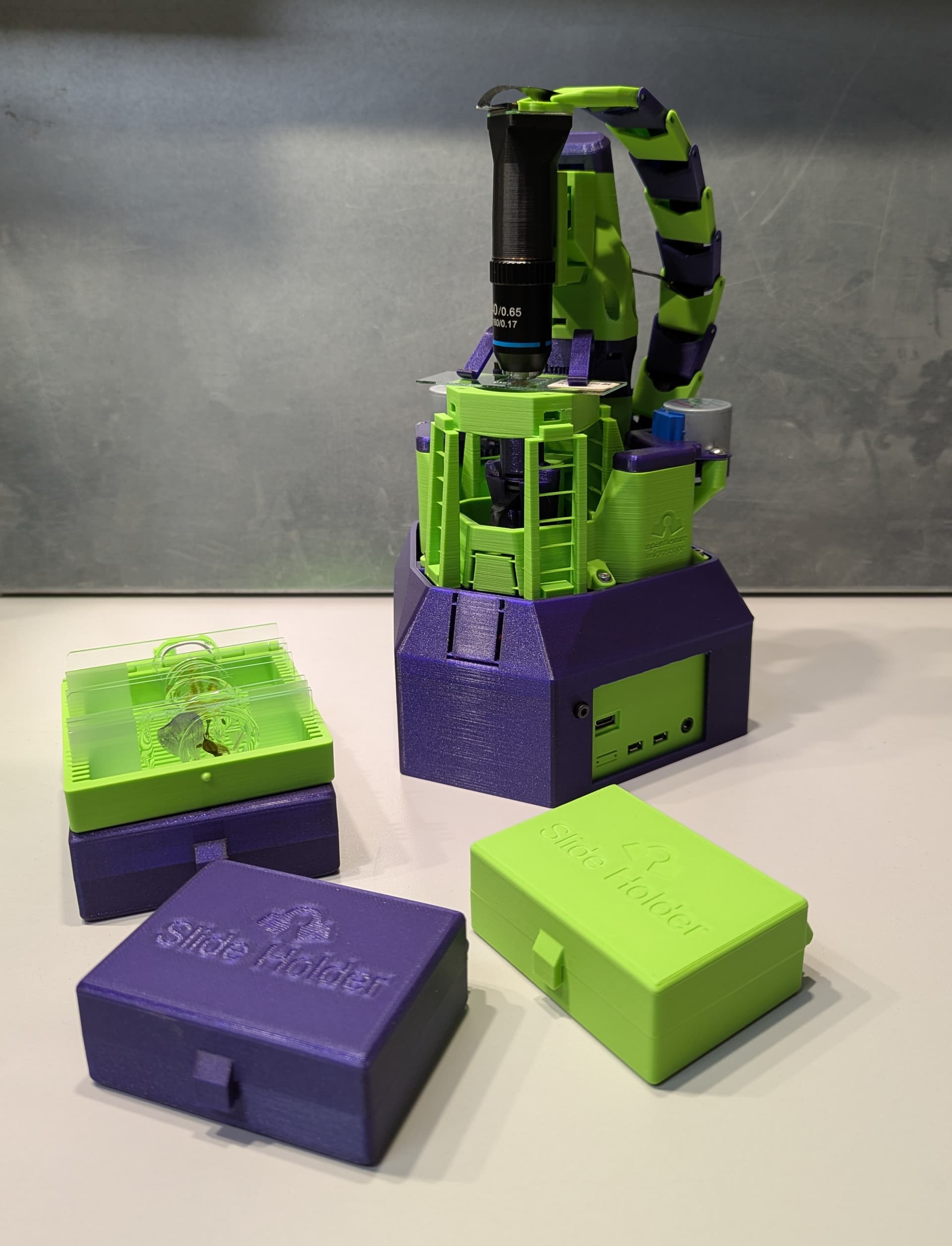
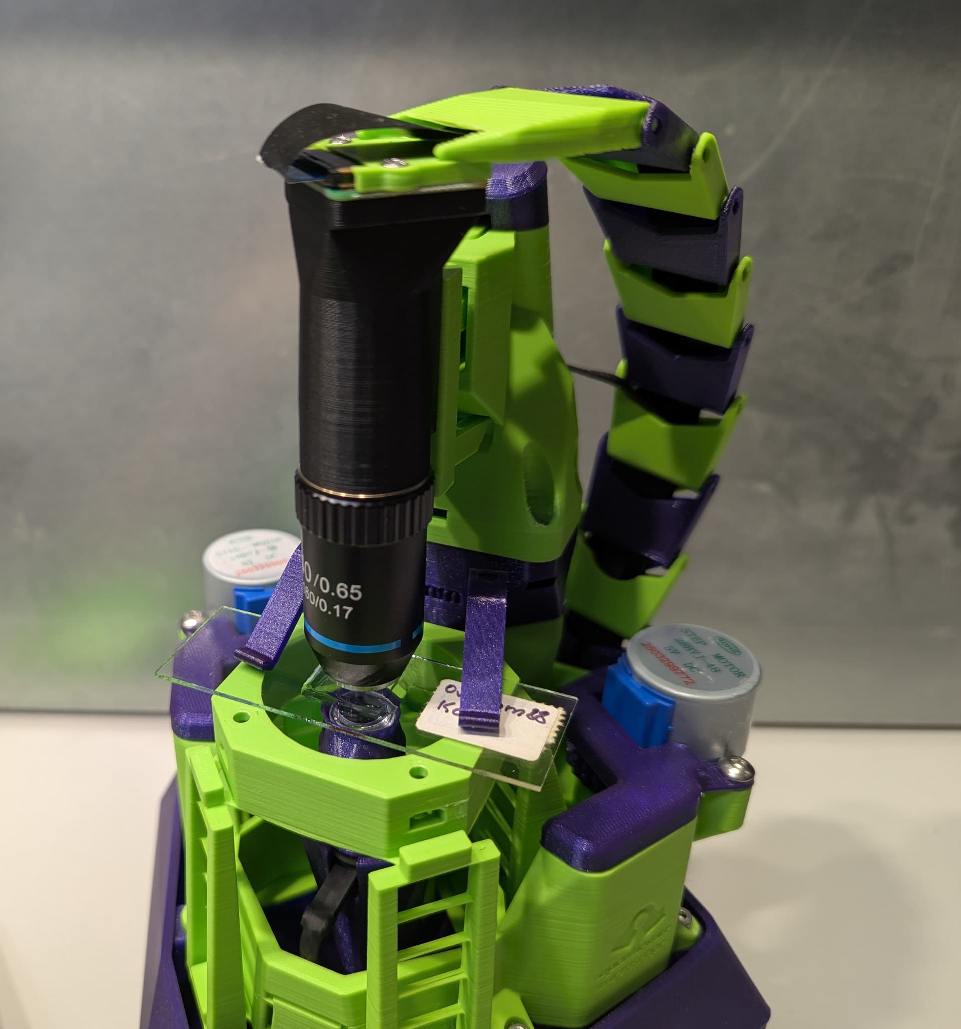
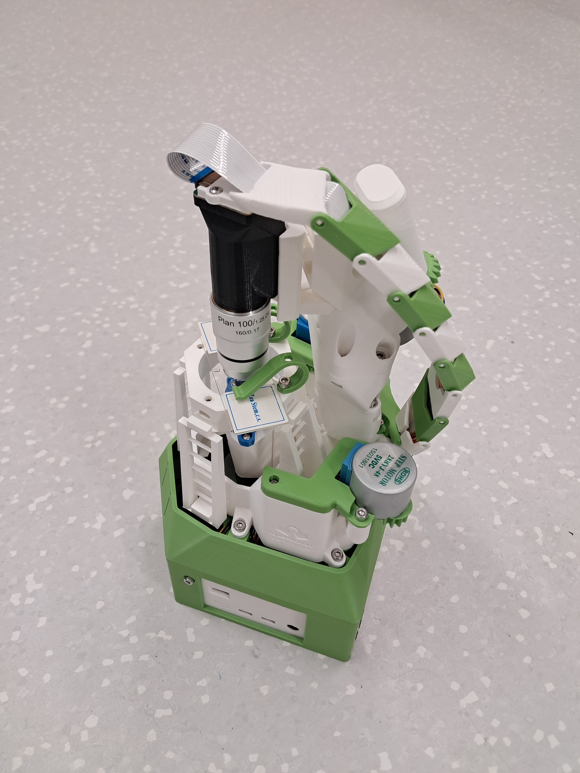
Dragchain for Upright Highres OFM with V7-Parts

As already shown in my build-report ( https://openflexure.discourse.group/t/build-report-of-second-build-high-resolution-upright-microscope-v7-hardware-v3-server/ ), I will share the files to print a dragchain for the Upright Highres-version.

The Files: unfortunately discourse does not allow much filetypes beside images, so you can download the files from this gitlab repo i just created. this is not something I am currently actively working on, this is just a place to drop the files. the .tar.gz in that repo contains all the rest of it.

Dragchain in action:

Details:

top-view:

bottom view:

the bottom part needed to be split and we got rid of the sidewalls of the inserting piece so that the picam-cable does not kink (it is basically as wide as the slot in the OFM). the center-pieces exist in 2 variants, one has a larger cavity to easier insert the z-motor-cable halfway in the chain.

Please feel free to use it however you like, we of course would love to see it incorporated into the official builds, i deliberately have choosen the same opensource-license.

However, in it’s current state, all the pieces have to be printed with tree supports and the printer must be able to print quite steep overhangs. We printed the parts on a Prusa CoreOne on PLA. This version is basically “for the looks”, but I am sure, the printability can be improved quite substantially.
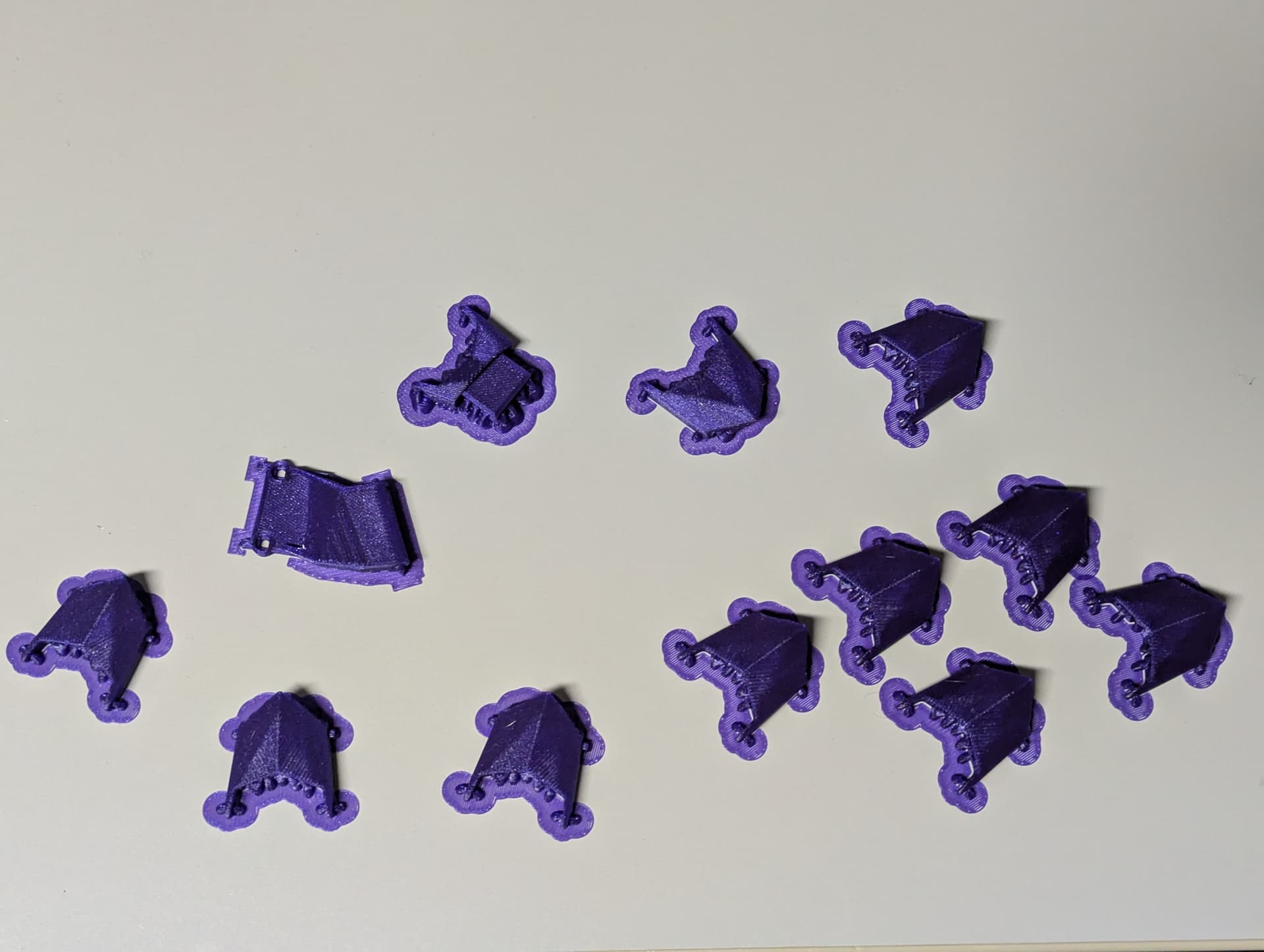
Have fun.

3 Likes

i just noticed, that while inspecting the regular upright low-res microscope, that the drag-chain most likely would work on that one, too. maybe minor modifications are necessary, but the camera-cover is fully open on both sides, so I think it “should” also work on the low res version. the drag chain cannot stretch to a fully horizontal arrangement because of the “scale-tip”, but in the other direction it can easily bend to 90°, so a tighter radius itself should not be a dealbreaker.

1 Like

This must be a typo. This obviously is a dragon chain.

3 Likes

did not thought about that. awesome :rofl: .

1 Like

Some updates:

We have now uploaded the drag-chain with some more generic end-pieces for general use to printables: Dragon Scale Drag Chain by pixel | Download free STL model | Printables.com . As you can see, it also looks very cool in a black and copper theme.

beside that, we also uploaded the drag-chain-version displayed here for the upright OFM (and others) to printables as well: Drag chain for a OpenFlexure upright microscope by pixel | Download free STL model | Printables.com

…happy printing.

2 Likes

@zeus I don’t know why I only ‘liked’ this before and did not comment, it is so cool.

When you first posted it we were in the middle of looking into changing the orientation of the Upright camera. We thought that the x and y axes would have to be the same for Upright and the standard inverted in order to work with our new scanning and stitching process. That would have made it harder to use this chain.

However, software changes have made the rotation unnecessary, and I have also started using my own Upright again. So I looked at your repository, rather than just the great photos here. It is very helpful that you have used OpenSCAD, which is not the easiest to use for design. The code looks to be very compatible with the main Microscope repository.

1 Like

You’re welcome. My wife and I usually use OpenSCAD for 3D-Designs, well before first hearing about the OFM the first time, because when you are familar with coding, it feels like the natural choice, even if many things that are typical for CAD-Design are very hard to pull off in OpenSCAD, while others are laughable trivial instead.

However, the problem or rather hurdles with the dragchain is, that you have two very intricate angles (at the start- and end-piece), and you cannot overdo it, because a flatflex-pcb only can handle so much kinking in the sideways direction (which is a deflection of preferably zero…). Beside that you have to somehow work around other moving parts. Because of that the dragchain has more aesthetic elements than purely necessary from a technical standpoint, because it was “not a very technical part” in the end anyways. Nevertheless, even though it is primarily not designed for printability, but for coolness-factor, i think it absolutely nailed it. The state in which the code is now is totally useable, however, for a solid integration to the main repo there may be some tweaks needed for more robust handling of geometry changes at the OFM itself and for scriptability. We however would absolutely love to see this integrated, because when looking at the pictures, in my opinion the drag chain feels absolutely natrual to the OFM and looks just awesome :slight_smile:

1 Like

…just before I forgot: meanwhile we also have a version of the top-part for the high-res-upright-OFM for the HQ-Camera. As expected it does also fit with some minor modifications of the top-piece…

I’ll upload it after cleaning up stuff a little…

1 Like

I forgot how much I dislike removing supports. The finish quality over supports on my Prusa Mk4 is also disappointing. Anyway all printed. As suggested, I used tree supports. I did supports only on build plate.

There is now a cover over the z-cable tidies for Upright. I modified that, but got the angle of the channel wrong, so I just hacked it.

Before and after:


Thank you!

1 Like

Looks good so far. Now that you have most of the cabling covered, it is interesting, how much the colored motor-cabled stick out. therefore we “painted” our cables with spray-rubber, but white heat-shrink-tubing, electrical tape or sleeving (as seen in gamery computer cables) would also cover it up.

However now you see the problem with the “angles” i mentioned, and what the maximum angle is, that the flexcable can kink. ideally you want to tilt every chain-link by the smallest amount (~0.5°) for a gradual slope, but that would be really hard to nail perfectly i think (and you would have to iterate a lot until this fits)…

btw: if you want a gradular curve over the links, and they end up a little too loose, you can insert a stiff cable on the inside as bendable stabilizer or something like that.

However, looks cool so far. :+1:

1 Like

I really like this drag chain. One niggle is that the angles on the microscope mean that the flat camera cable needs to start from the camera at one angle and then needs to end at the cable channel at a different angle, and also displaced slightly, which gives kinks.

So I started thinking about how to do this smoothly using out of plane bends. This is where I have got to. The red part gives the two bends calculated to make the angle change and sideways translation to meet the position and angle of the chain. The white cover over the top makes it look a bit neater.

I think it might work. The drag chain would clip to an extension of the red part.

(Progress will be in the Merge Request !537)

[edit: This is the image that @zeus mentions below for the basic idea, from that merge request:

]

1 Like

you should’ve added the image from the merge request, as it makes the intent much clearer.

(edit: he’s done that :slight_smile: …)

anyhow, this is a really interesting solution to solve that problem without kinks at all.

our design for the drag chain was based on a very gradual curve over the whole length. this is not ideal, but i don’t think it stresses the cable toooo much. however, this here is a very interesting take on displacing and flipping the cable basically at will.

In your build the cable does lie well through the drag chain. I get a kink between the white top piece and the first green link:


Your images only show this section from above, but it does not seem to be a problem for you. In your build it looks as though you have folded the cable quite tightly back on itself at the camera, I have left mine in more of a curve. This might be making a sufficiently different angle of entry into the top piece? Or should I have tried to wiggle that kink down into the first green link?

It seems that I can adjust the kink out of that gap:

But there is still a kink, it is out of sight

yeah, also on our scope it is certainly not “kink-free”, but i don’t worry too much about that, because there is not much movement in the chain during normal use. the reason you normally want to have a 100% kink-free chain is because drag-chains/energy-chains usually travel together with one of the axis, which is not the case here.

anyways, every “proper” solution, like yours, is certainly more favorable than just bending it around the curve. the bend was a neccessary evil to make the chain happen in the first place, however i did not even thought about rolling it around two cylinders to achieve free angular placement…

1 Like

I was looking at the dragon chain @WilliamW printed when I was in his lab last week. I had the idea of trying to make a dragchain that prints as a single piece without support.

My first attempt was a bit tight as I forgot to take into account that the cable isn’t infinitely thin, I got the cable in eventually:


The lack of assembly (and the need for assembly renders) and the lack of supports is certainly nice. The actual chain itself is considerably less pretty than @zeus’s dragon chain. Also it is limited to 1 colour unless you have a multi-material printer.

I have added a bit more clearance (not yet tested) and opened an MR

2 Likes

I also already considered print-in-place, however I opted against it, because the major drawbacks would be, that

  • a: This would only work for the ribbon cable, not additionally also the motor-cable (however, it could be mounted with integrated clips on the outside of the drag chain, but it would defeat the purpose of a drag-chain all together)
  • b: this would not allow for changes in overall height of the microscope outside a relatively narrow height-window. If you want to use a much longer optic or lighting-solution which requires the tube to be much longer, the chain would certainly be too short. printing additional links as single objects would make the PIP-option obsolete in the first place.

I guess ach of those point could be workarounded, but yeah, a “one size fits all” solution would be quite challenging (but those who decided to print the upright version are already beyond that point anyways I guess…).

edit: to “a”: considering the pictures, the slot does not look tooo narrow. when not twisted it looks like the motor cable might actually be able to pass through. however, it certainly would have to be de-pinned and beeing inserted strain by strain, which is a pain and hassle and completely destroys easy repairability… however, it looks like as it could at least fit… (an other option would be just a JST-XH-Extension cable. it would also have to be depinned, but can remain inside the chain on disassembly…)

1 Like

Thanks @zeus. I had not realised that the motor cable was also going in the drag chain. I’ll need to check with @WilliamW what his plans are for the z motor cable.

I think on point b, that is a difference between a prototyping and a production decision. I think if the chain is going to be used as standard for the standard builds of in the instructions having a fixed length is useful. For a prototyping microscope where the objective height is moving then it is certainly very handy to be able to adjust the length.

Update, now more dragon-y:


1 Like

actually i don’t think the 3-shim-hinge-design (in lack of a better description) does the chain any favor. by placing three thin walls side by side it certainly looks more like a “production-design”, but I don’t think it is particularly suitable for 3d-printing. When printing them as single links, they might break easily on insertion, when printing as PIP, they may ruin the print all together (like all small features sticking out upwards, at least there is a decent chance for that unfortunately).

In injection molding, where less material is better, this makes total sense (and that’s the reason we see this often), but on 3d printing, having one thick wall is much more favorable than two narrow ones. interlocking can easily be done with positive and negative cones. when multiple links printed “in-place” side by side, the angle can also be quite steep, because the other cone surface basically acts as support, when the gap is not too wide. This is one of the most challenging things in 3d-printing in general, that when designing parts, you always have to account for the intended manufacturing method. that is why so many printed objects are so incredibly brittle and unstable, because they are mostly designed with injection molding in mind (for example by copying existing designs). In 3D-printing, having thick chunky designs is totally fine, because they mostly are just a stable shell with some infill for structural rigidity, but 90% of the strength comes from the shell. most of the support is just there to increase printability. I am 3D-printing since ~2010 or somewhere around that (at a time where you just couldn’t buy printers, you had to build one yourself instead, and they were often somewhat yank to say that friendly). I’ve sticked myself to “traditional injection-molding-design-philosophy” much, much longer, than I’d like to admit to, but shifted the paradigm eventually.

for sure, the dragon chain is purely aesthetic in the first place and also does not follow what i said above, but I always try to keep the manuf.-process in mind, because it often makes thinks much easier as they look like at first.

There are also many other interesting things one could try out. For example, i also thought about small round neodymium magnets as hinges. certainly overkill for a drag chain, but in terms of coolness and also repairability way ahead of many others (however, it might have negative impact on unshielded data-cables…).

the “low-poly-aesthetic”, which is very similar to the “dragon chain” approach, however looks very appealing.

Thanks @zeus,

I certainly agree we need to think about how things are being made. I learned this the hard way when I first started making my own components on the mill and the lathe when the central workshop was backed up at NIST. Each step of an OpenFlexure design is always done with the FDM process in mind. The 3rd shim exists to create opposing surfaces that can be bridged between to create the print in place mechanism with no need to build in supports that break on first actuation.

“Production” is perhaps a misleading term. OpenFlexure production is distributed across the world, to 100s of people with a 3D printer, generally with very little communication back to the core team. As such I tend to focus on some core principles:

  • No slicer support needed. This is partly a hold over from support being much worse in the past, but it means people need to think about print settings per part, which is much harder to communicate in instructions.
  • Minimal assembly Fewer parts to describe, fewer steps to describe, fewer images to render. These all increase accessibility, an minimise on going work for our team.
  • Minimising push-fits Early OpenFlexure designs had a lot of push fits. They could be tested loads on our printers and work fine, but in the wild when we visited people who had made them we would find some too loose, some too tight.

Not saying this to imply that this way is inherently better than other design philosophies. Just that this is the philosophy that we have adopted, and try to stick to based on our own experiences. Probably at some point we should write a bit of a “OpenFlexure design approach” guide, in the same way we have recently written (but not heavily promoted) a our OpenSCAD conventions.

Carrying on with the evolving design. I have made it a bit taller to give wire space and made some zig-zag channels that allow the motors in, but make it hard for them to fall out:


I also did some stress testing of the hinges (throwing it around the room, and hitting things with it, nothing well calibrated). They survived pretty well until I amped up the severity, but my printer is reasonable well tuned (but 6-7 years old). For good measure I beefed up the hinges too.

2 Likes