@BRENDY77 that is a nice video. It is really helpful to have some more on the software side as well as the hardware. The images of samples at the end are not as clear as I would have expected. There could be two reasons for that. Did you use the lens spacer from the V7.0.0-Beta release? There is a known problem with the lens mount in that part, which is noted in the bugs post on Openflexure Microscope V7.0.0-beta1 released. With the part released in the Beta, the lens is not fixed at the right distance or the correct angle, it will be about right but the angle offset causes poor image quality. You can actually see the problem in the cut-away image on the instructions Assemble the basic optics module, in the right-hand cutaway render, where the inner support does not reach the lens https://build.openflexure.org/openflexure-microscope/v7.0.0-beta1/renders/low_cost_optics_assembly_pi_lens.png.
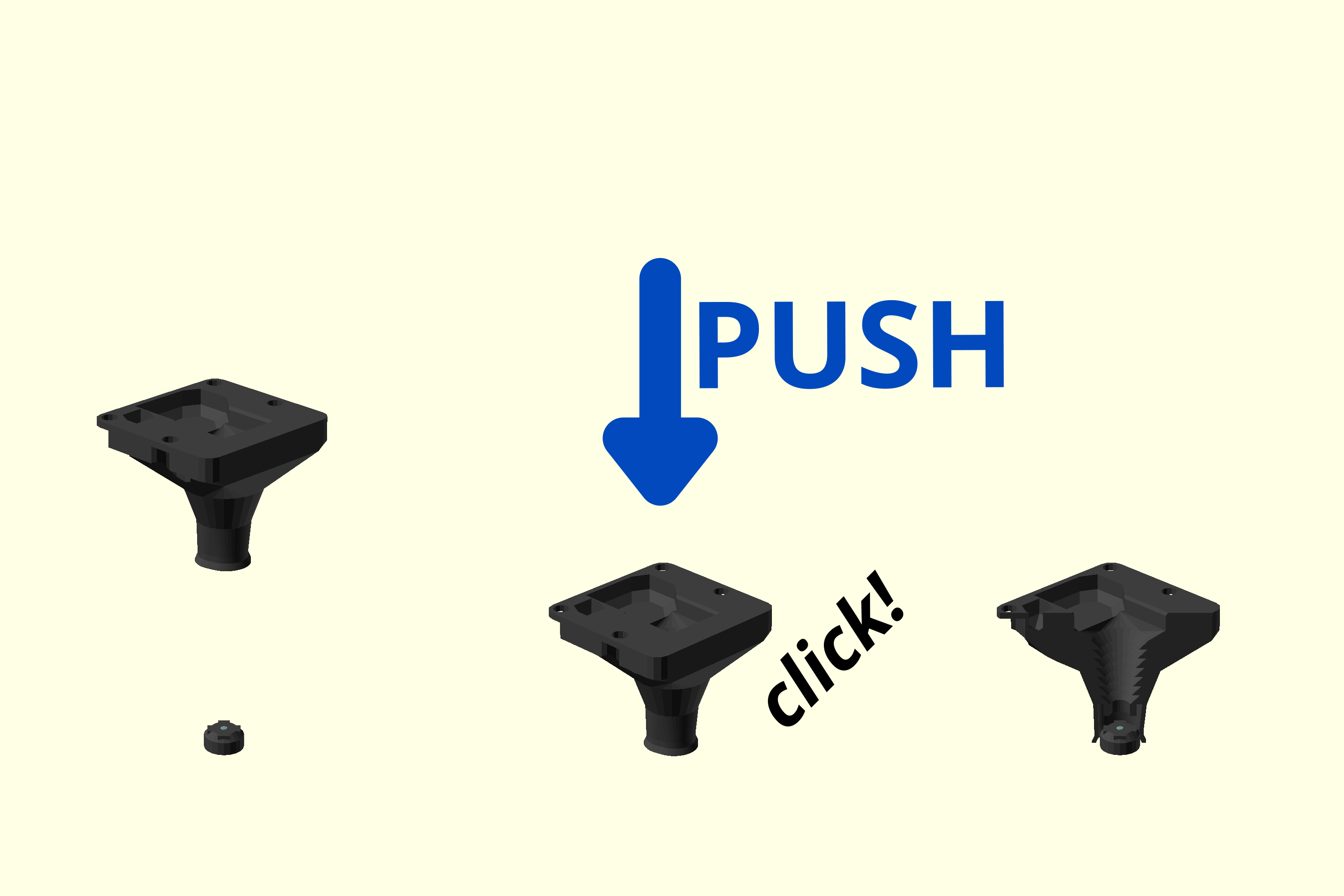
The second cause could be that the lens is placed the wrong way round in the lens spacer (shown at 1:50 in the video). The side that was facing the camera should be outwards, which is the side without the cross-shaped moulding. In normal use the object is a long distance away, and the image is formed on the camera sensor very close to the lens. This asymmetrical imaging means that the lens is not symmetrical internally. In the microscope it is the sample that is close to the lens (~1mm) and the camera sensor is relatively far from the lens (17mm is not very far, but still much further than 1mm).