I have two main issues that I am hoping to get help with. For some background, I purchased the OpenFlexure Microscope through the ioRodeo vendor, and used all of their default equipment, settings, etc. for the High-Resolution version with the 40x objective lens and the 50 mm achromatic ThorLabs lens, all provided through ioRodeo.
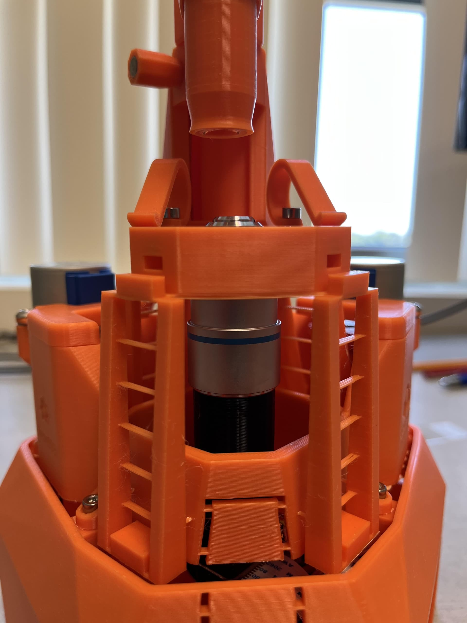
After assembly, the microscope objective lens pokes out the top of the staging area (pictured). This makes it impossible to stage a slide. I had to manually rotate the Z gear to bring the objective below the level of the stage. This poses two additional issues: first, why is it possible for the objective lens to have this range of motion past the stage? Did I assemble the microscope incorrectly? Second, with this range of motion, it seems the Z motor will be able to push the objective lens past the stage and into a slide, potentially damaging both. Surely, this can’t be an intended feature.
Upon running OpenFlexure Connect for the first time, I was prompted to allow a calibration, which proceeded to move the slide in the X direction 33,000+ units. Because the image was not clear, the microscope continued moving until I could hear the 3D-printed stage cracking under pressure. I now believe that the software does not know what the starting value of coordinates are and that it will continue moving the stage in directions beyond nominal tolerance levels. Am I missing a “zeroing” step, wherein the microscope zeros out the coordinates before doing anything? How do I avoid the microscope pushing the stage past tolerance ? (To be clear, I have since run the calibration with a clear image. I am asking about the tolerance issue here.)
@Shay welcome, I am sorry it has taken a while to reply. Thank you for the detailed feedback on setup of your microscope. Going to the second point first, we are working on better software awareness of problems happening in the calibration for the next software release (v3). Until that is ready it would be useful to have another step in the instructions for the initial centering and preparation for calibration. There is no position detection in the microscope, but the position is saved in the Sangaboard, so if it is zeroed to start with then the position is known readonably well. At present the initial centering is putting the microscope actuators in the same position that they were when printed - with the nut slots aligned with the hole in the actuator casing.
Just fyi, I had the same problem as your #1 with the components from iorodeo, The openflexure instructions tell you to “Slide the optics module up the keyhole as high as it will go”. Step 1, Mount the optics. This does not work for the iorodeo parts. You have to loosen the screw again, move the optics lower so that it doesn’t interfere with the stage. I put a slide on the stage, and then raised the optics until it was just a fraction of an inch below the slide, and then retightend the screw. (And the slide has to be upside down, so that the slip cover faces down.)
This is hard to do with only two hands, you might need help. I had a lot of difficulty finding the exact position for the optics such that the microscope could focus, it took me a number of tries, and I still don’t have it perfect, but I was eventually able to get the microscope to focus on a slide. It would be ideal if the design had a thumbwheel on the optics component, such that you could move it up and down in very fine amounts, making it easier to get to the proper focal spot.
The image must be reasonably clear before you run the calibration, otherwise it will just march along until it hits the end of the motor range.
For your first point, again it is partly about the initial setup. With the z-actuator in the default central position the lens should be close to the correct focal place.
Because the design works with high resolution microscope objectives, up to oil immersion 100x, the working distance can be less than 0.1mm. In that case it is not really possible to make the microscope physically unable to touch the slide while also being certain that you can get close enough to the slide to focus. This is the same in conventional microscopes, and most high resolution objectives are in sprung mounts to try to minimise the affect of accidentally moving to touch the slide. There still remains a requirement for the user to be aware of the lens height.
What I have noticed in playing with the z-axis today is that the ‘up’ motion actually goes quite a bit further than the design range. The total motion in z should be about 2mm 4mm, 1mm 2mm below centre and 1mm 2mm above.
When I drive the z gear by hand clockwise it raises the actuator column until it hits the inside of the top of the actuator housing. At that point the optics dovetail has moved about 1mm 2mm down.
When I drive the z gear by hand anti-clockwise it lowers the actuator column. The gear keeps turning beyond the ~4 turns needed for 1mm 2mm upwards movement of the optics dovetail. The band tension begins to feel weaker, but the actuator keeps on moving until the bottom of the actuator column hits the inside of the foot. At that point the optics dovetail has moved about 5mm up.
Again a bit more in the instructions would be useful, and possibly a shorter hard stop in the foot.
(edited: My memory of the actuator lever ratio and range was wrong it is 1:1. My estimate of small travel distance by eye was also wrong)
This ought to be correct, with the actuator in the central position. The position of the hole was set before the first alpha release, so all v7 Microscope bodies should be the same in that regard.
It would be useful to have a picture looking at the z-actuator nut hole of your microscope when it is focussed on a flat slide.
We should also think about instructions for stage centring.
Also the first cal wizard should actually make sure that the user is able to get the sample in focus before starting camera stage mapping. This is a problem still in v3, the first time you run your microscope it asks “put a sample in and click go”. We are to used to exiting out of it, focussing, then running camera stage mapping. Really mapping should first ask the user to focus and bring up tools to do so. I’ll open an issue on this.
WilliamW: At the moment I am seeing a kernel panic each time I apply power to the microscope, not sure what is going on. When I get that figured out, I’ll send the picture. To satisfy my curiosity, in your microscope what is the exact length from the top of the optics module to the top of the microscope objective? Measuring from the point where the black module meets the objective to the top of the objective in my case is 4.5 cm. My hypothesis has been that my objective is longer than yours.
The 45mm that you have measured is called the ‘parfocal distance’. The Openflexure Microscope is designed for 45mm parfocal distance, which is the most common standard. There is also a 35mm standard.
45mm should be the distance from the “shoulder” to the focus, we call this the par focal distance. For a 40x objective the working distance (from the top of the objective to the focus plane) should be about 0.4mm so I’d expect your objective to be about 44.6mm long. So, it sounds like everything is correct.